Category: Materials & Processes

Material selection and process capability for custom metal parts. Stainless steel, aluminium, copper and steel grades compared by formability, corrosion resistance, machinability and cost.

  • Progressive vs Compound vs Transfer Die: Choosing Stamping Tooling

    Tooling choice determines most of what a stamped part will cost over its lifetime, and it is decided before the first piece is ever made. The progressive die vs compound die comparison comes down to how many operations you need to combine and how fast you need to produce: a compound die performs several operations in one station on one stroke, while a progressive die moves a strip through a sequence of stations and delivers a finished part every stroke once the strip is loaded.

    Alongside those two sit single-stage tooling — the simplest and cheapest to build, the slowest and most labour-intensive to run — and transfer tooling, which mechanically moves individual blanks between stations and handles parts that cannot stay attached to a carrier strip.

    Choosing well is not about picking the most sophisticated option. It is about matching tooling investment to realistic annual volume, part complexity and how stable the design is. This guide sets out the trade-offs so the decision can be made on engineering grounds rather than on whatever the supplier happens to own.

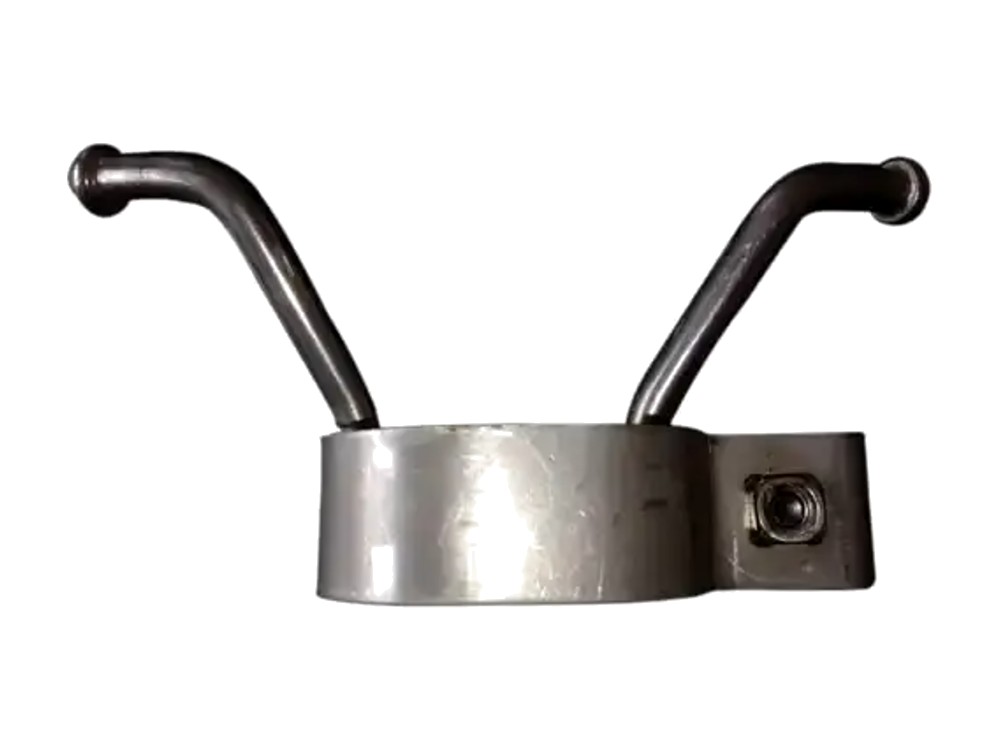
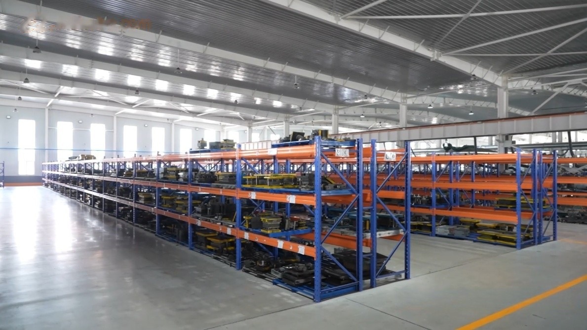
    Progressive die vs compound die stamped components produced at XCWY
    Stamped components from XCWY progressive and compound tooling

    The four tooling types

    Single-stage tooling

    One die performs one operation. The part is blanked in one tool, then moved to another for piercing, then another for forming. Each step is a separate setup, and usually a separate handling operation by an operator.

    The tooling is inexpensive and quick to build, and any single step can be modified without touching the rest. The penalty is recurring: handling labour on every piece, accumulated positional error between setups, and slow throughput. Single-stage tooling suits prototypes, low volumes and parts whose design has not settled.

    Compound die

    A compound die performs multiple cutting operations at a single station on a single stroke — typically blanking the outline and piercing the holes simultaneously. Because everything happens in one hit with the material held in one position, the relationship between the outline and the holes is exceptionally consistent.

    That is the compound die’s defining advantage: concentricity and feature-to-feature accuracy. Its limitation is that it is primarily a cutting tool. Complex forming is not what it does, so parts needing several forming stages will still require secondary operations.

    Progressive die

    A progressive die contains a sequence of stations. The strip advances a fixed pitch with each stroke, and the part is progressively cut and formed while remaining attached to a carrier strip until the final station cuts it free. Once the strip is running, a finished part leaves the die every stroke.

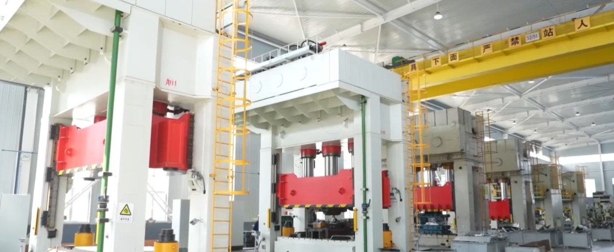
    Progressive tooling delivers the lowest cost per part at volume and the highest throughput. It is also the most expensive to design and build, the most demanding to maintain, and the least forgiving of design changes — altering one feature can mean reworking several stations and re-timing the strip layout. Our stamping operation runs progressive and compound tooling across a 25 to 400 ton press range, with die design and build handled in our own workshop.

    Transfer die

    In transfer tooling the blank is cut free at the start and then moved mechanically from station to station by transfer fingers. Because the part is not attached to a carrier strip, it can be formed on all sides, turned over, and drawn deeply — geometries a progressive die cannot accommodate.

    Transfer tooling suits larger parts, deeper draws and shapes where a carrier strip would obstruct the forming. It is slower than progressive per stroke and the transfer mechanism adds cost and complexity, but for the right geometry there is no alternative.

    Progressive die vs compound die: choosing between the two

    These two are the ones most often confused, so it is worth stating the difference plainly.

    • Operations per stroke. A compound die performs several operations at one station simultaneously. A progressive die performs one operation per station, sequentially, across many stations.
    • Output per stroke. Both produce one part per stroke in steady state, but the progressive die can incorporate far more operations in that single stroke’s worth of throughput.
    • Accuracy character. The compound die’s single-hit approach gives it the edge in hole-to-outline concentricity. A progressive die accumulates a small amount of positional variation across stations, controlled by pilot pins that locate the strip at each step.
    • Forming capability. The compound die is essentially a cutting tool; the progressive die readily combines cutting with bending, embossing, coining and shallow drawing.
    • Tooling cost. A compound die is significantly cheaper to build than a progressive die of comparable part complexity.

    The practical rule: if the part is a flat cut part with demanding concentricity and no meaningful forming, a compound die is usually the better value. If the part needs several forming operations and the volume justifies it, the progressive die repays its cost through cycle rate and eliminated handling.

    Decision table

    Criterion Single-stage Compound Progressive Transfer
    Operations combined One per tool Several cutting ops, one station Many, sequential stations Many, part moved between stations
    Relative tooling cost Lowest Low to moderate High High
    Tooling build time Shortest Short to moderate Longest Long
    Cycle rate Low Moderate Highest Moderate
    Handling labour per part High Low Minimal Low
    Forming capability Yes, one stage at a time Limited Extensive Extensive, including deep forms
    Concentricity control Weakest Best Good, pilot-controlled Good
    Material utilisation Variable Good Carrier strip is scrap Good, no carrier strip
    Tolerance of design changes Highest Moderate Lowest Low
    Best-fit part type Prototypes, low volume, unsettled design Flat cut parts needing tight concentricity Complex cut-and-formed parts at volume Large or deeply formed parts

    Progressive die vs compound die: volume thresholds

    There is no universal part count at which progressive tooling becomes correct, and any supplier quoting one is generalising. The break-even depends on part complexity, material cost, press rate and how much handling labour the simpler route requires. What can be stated as engineering guidance is the direction of the trade-off:

    1. Prototype and pilot quantities. Single-stage tooling, or laser cutting and bending with no hard tooling at all. Committing to a progressive die before the design freezes is the most expensive mistake available.
    2. Low, uncertain volumes. Single-stage or compound tooling. Keep the fixed investment small while the programme proves itself.
    3. Established medium volumes. Compound tooling for cut parts, progressive tooling where forming operations are stacking up and handling labour is visibly dominating cost.
    4. High, stable volumes. Progressive tooling almost always, unless geometry forces transfer.

    When annual volume is genuinely uncertain, a staged approach is often the rational answer: build simple tooling first, produce and sell, then invest in progressive tooling once demand is demonstrated. The first-year part cost is higher but the downside is bounded. Committing to expensive tooling for a forecast that does not materialise converts a variable cost into a stranded one.

    Material utilisation and scrap

    Scrap is a recurring cost that quietly outweighs tooling on high-volume parts. Progressive tooling carries an inherent penalty here: the carrier strip that holds the part between stations becomes scrap. Depending on part geometry and strip layout, that can be a meaningful share of the material purchased.

    Transfer tooling avoids the carrier strip entirely, which is one reason it can win on large parts where material is a bigger cost driver than cycle time. Compound tooling nests reasonably well because the outline is cut in one hit.

    Strip layout is where a die designer earns their fee. Part orientation, nesting angle, web width between parts and pitch all affect how much of the coil ends up as product. On a long-running part, a two or three percent improvement in utilisation can exceed the entire tooling cost over the programme life.

    Maintenance, die life and first article lead time

    Every die wears. Punches dull, edges chip, clearances open up and burr height creeps. A maintenance schedule based on strokes rather than on the appearance of defects is the difference between planned downtime and an unplanned stoppage mid-order.

    Progressive dies demand the most attention because a single worn station affects every part, and because re-timing after a repair requires care. Compound dies are simpler to sharpen and reset. Single-stage tools are trivial to maintain but you have more of them.

    On lead time, expect the tooling build to dominate the schedule for any hard-tooled part. Single-stage tooling is fastest, progressive slowest. First article inspection then adds a review cycle before production release — a step worth protecting, since approving a first article properly is far cheaper than discovering a dimension problem after ten thousand parts. Our inspection sequence is described on the quality page.

    Design decisions that affect tooling choice

    • Hole-to-edge distance. Holes placed closer than roughly two material thicknesses from an edge or bend can distort during cutting or forming.
    • Uniform hole sizes. Standardising hole diameters reduces the number of punches and simplifies maintenance.
    • Generous internal radii. Sharp internal corners concentrate stress in the tool and shorten die life.
    • Symmetry. Symmetric parts nest better and are less prone to strip-feeding problems.
    • Tolerance discipline. Tight tolerances applied to non-functional dimensions raise tooling cost and inspection cost with no benefit. Tighten what locates or mates; relax the rest, using a general tolerance class such as those in ISO 2768 for everything else.
    • Forming direction. Bends in a single direction simplify progressive strip layout; bends in opposing directions may push the part toward transfer tooling.

    If the part might not need hard tooling at all, that is worth establishing early — for low volumes, laser cutting and CNC bending produce the same geometry with no tooling investment whatsoever.

    Frequently Asked Questions

    What is the difference between a progressive die and a compound die?

    A compound die performs several cutting operations at a single station in one stroke, while a progressive die performs one operation per station as the strip advances through a sequence of stations. The compound die gives the best hole-to-outline concentricity; the progressive die combines far more operations and produces complex formed parts at higher rates. Compound tooling costs considerably less to build.

    When is progressive tooling worth the investment?

    Progressive tooling pays off when volumes are high and stable and the part needs several operations that would otherwise require separate handling. The break-even depends on part complexity, material cost and press rate, so it should be calculated per part rather than assumed. If the design is still changing, defer the investment.

    Can a progressive die produce formed features as well as cut ones?

    Yes. Progressive tooling routinely combines blanking, piercing, bending, embossing, coining and shallow drawing across its stations. This is its main advantage over a compound die, which is essentially a cutting tool.

    What is transfer tooling used for?

    Transfer tooling is used when the part cannot remain attached to a carrier strip — typically large parts, deeply drawn shapes, or geometries that must be formed on multiple sides or turned over. The blank is cut free first and mechanically moved between stations. It also avoids carrier-strip scrap, which matters on large parts.

    How long does stamping tooling last?

    Die life depends on material hardness, tool steel selection, coating, clearance and maintenance discipline rather than on a fixed number. Punches and die inserts are consumable and are sharpened or replaced on a planned schedule based on stroke count. Well-maintained tooling can run for many production years, which is why maintenance planning matters more than the initial specification.

    Who owns the tooling I pay for?

    That depends entirely on the contract, and ownership terms vary considerably between suppliers. Establish in writing, before the tooling order is placed, who owns the tooling, whether it may be used for any other customer, and how it is released if you change supplier. Ambiguity here becomes commercial leverage against you at every later negotiation.

    Send the part and the volume, and we will recommend the tooling

    Tooling selection is much easier to get right when the drawing and the realistic annual volume are reviewed together. Send both and an engineer will recommend a tooling route, flag any features driving unnecessary die complexity, and return a quotation within 3 business hours. Email xcwystamping@xcwybj.com or use the quote request form.

  • Powder Coating vs Anodizing vs Electroplating vs Passivation: Choosing a Metal Finish

    The finish decision is constrained before preference enters into it, because each process only works on certain base metals. Anodizing is an aluminium process. Passivation is a stainless steel process. Electroplating works on conductive substrates, most commonly steel. Powder coating is the only one of the four that works on essentially any metal that can survive the curing oven. So the powder coating vs anodizing comparison only arises when the part is aluminium — on steel, anodizing is simply not an option.

    Once the base metal narrows the field, three questions decide the rest: does the finish need to conduct electricity, how much dimensional build-up can the part tolerate, and what corrosion environment is it going into? Answering those three in order resolves most specifications quickly.

    This guide covers what each process does, where it fits, and how to write a finish callout that a supplier can actually quote against.

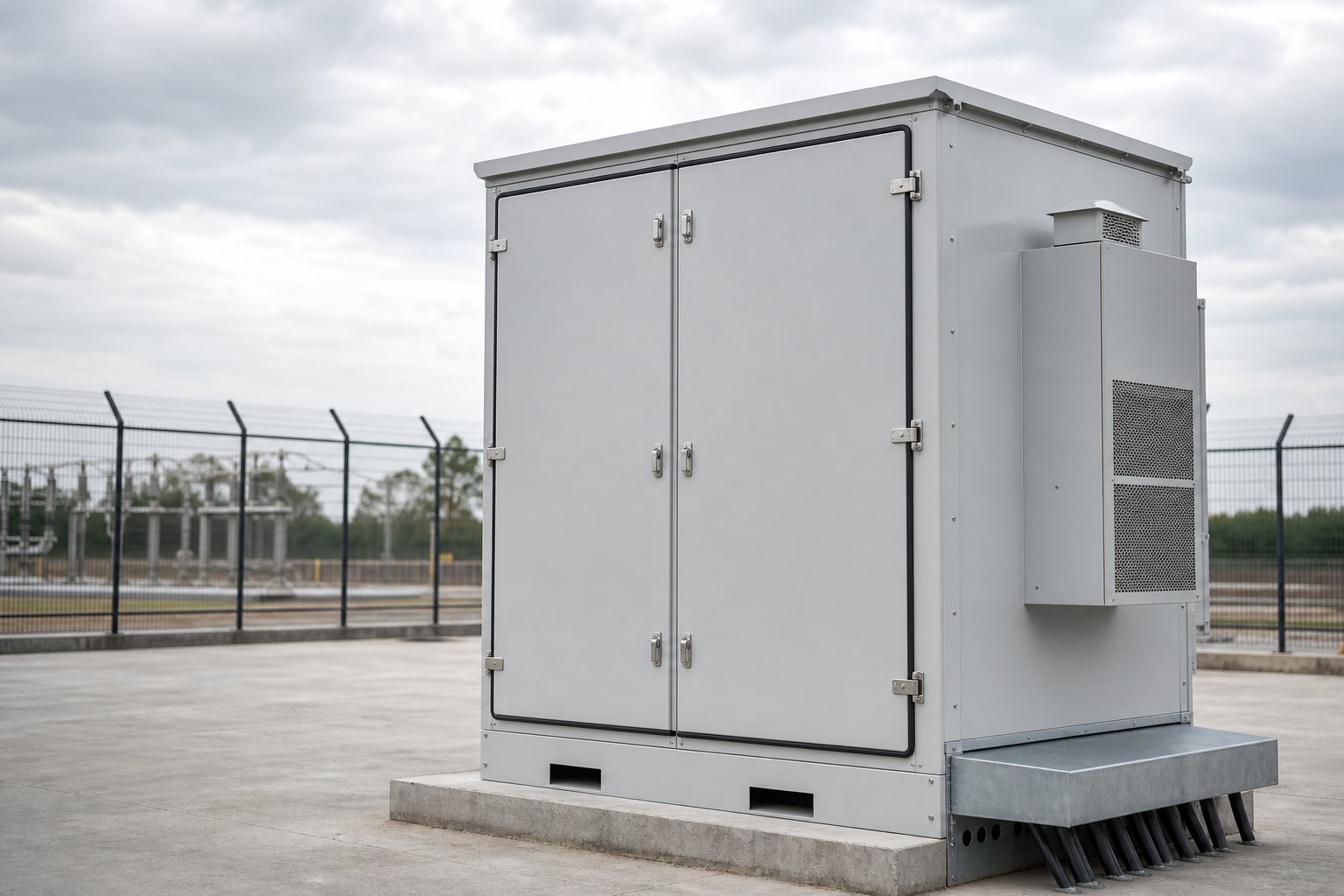
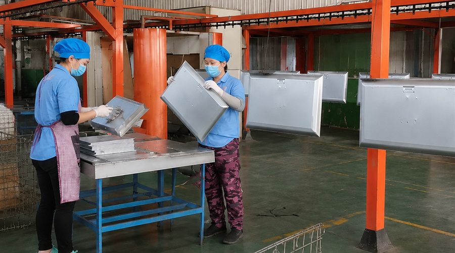
    Powder coating vs anodizing - finished metal enclosure produced at XCWY
    A finished metal enclosure produced at XCWY

    What each finish is

    Powder coating

    Dry polymer powder is applied electrostatically to a grounded part and then cured in an oven, where it melts and flows into a continuous film. The result is a thick, tough, fully opaque coating available in an enormous colour and texture range.

    Powder coating is a barrier finish: it protects by physically separating the metal from the environment. That makes surface preparation decisive — a coating over contamination or scale will look perfect and then fail from underneath. It is also an electrical insulator, which matters more often than people expect on enclosures requiring earth continuity.

    Anodizing

    Anodizing is an electrochemical conversion process for aluminium. The part becomes the anode in an acid electrolyte and the surface converts into a hard, porous aluminium oxide layer, which is then sealed. The oxide layer is not applied on top of the metal — it grows out of it, so it cannot chip or peel the way a coating can.

    Type II sulphuric anodizing is the general-purpose decorative and protective option and accepts dye colours. Type III hard anodizing produces a considerably thicker, much harder layer for wear resistance. Anodizing is an insulator, and it builds dimension: as a working rule, around one third of the oxide layer penetrates into the metal and two thirds grows outward from the original surface, so a hard anodized part gains measurable size on every coated face.

    Electroplating

    A metal layer — zinc, nickel, chrome, tin, silver or gold — is deposited electrolytically onto a conductive substrate. Zinc plating is the workhorse for steel corrosion protection and is normally followed by a chromate or passivate conversion coating that substantially extends its life. Zinc protects sacrificially: it corrodes preferentially and shields the steel beneath even where the layer is scratched.

    Plating is thin, so it preserves dimensions and fine detail, and it remains electrically conductive — the reason tin and silver plating are used on electrical contacts and busbars.

    Passivation

    Passivation is not a coating at all. It is a chemical treatment for stainless steel that removes free iron and other contaminants from the surface and encourages the natural chromium oxide film to reform uniformly. Nothing is added and dimensions do not change.

    It matters because machining, grinding, welding and even handling with carbon steel tools can embed iron particles into a stainless surface, and those particles rust and initiate localised attack. Where welding has produced heat tint, pickling is used first to remove the chromium-depleted oxide layer, and passivation follows.

    Powder coating vs anodizing on aluminium

    When the part is aluminium and both are available, the choice usually turns on four points.

    • Colour. Powder coating offers essentially unlimited colours, including exact RAL matching, plus textures and gloss levels. Anodizing colour comes from dyeing a porous oxide layer, giving a narrower, more metallic-looking palette that can vary between batches and alloys.
    • Appearance of the substrate. Anodizing is translucent, so the metal’s grain and any surface defects remain visible. Powder coating hides the substrate completely, which is either an advantage or a loss of character depending on the design intent.
    • Wear resistance. Hard anodizing outperforms powder coating substantially on abrasion and cannot chip, because it is integral to the metal. Powder coating is tough but can chip on impact at an edge.
    • Edge coverage. Powder coating tends to thin at sharp edges, which is where coating failures usually start. Anodizing grows uniformly over the whole surface including edges.

    For outdoor architectural and enclosure work in a specific colour, powder coating usually wins. For functional aluminium parts needing wear resistance, dimensional stability and a metallic appearance, anodizing usually wins. Both are handled as part of our surface finishing stage, in the same plant as fabrication.

    Comparison table

    Attribute Powder coating Anodizing Zinc electroplating Passivation
    Base metals Most metals Aluminium only Steel and conductive substrates Stainless steel only
    Nature of finish Applied polymer film Converted oxide layer Deposited metal layer Chemical surface treatment
    Typical thickness 60 – 120 µm 5 – 25 µm (Type II); 25 – 115 µm (Type III) 5 – 25 µm No measurable build-up
    Dimensional impact Significant Moderate, half grows outward Small None
    Electrically conductive No — insulator No — insulator Yes Yes
    Corrosion protection Barrier — good if preparation is sound Good, excellent when sealed Sacrificial — protects scratches Restores stainless passive film
    Colour options Extensive, full RAL range Limited dyed range Clear, blue, yellow, black chromate None — appearance unchanged
    Abrasion resistance Good Very good, excellent hard anodized Moderate Not applicable
    Chip or peel risk Possible at edges and impacts Very low — integral to metal Low Not applicable
    Relative cost Low to moderate Moderate Low to moderate Low

    Powder coating vs anodizing on corrosion protection

    Salt spray testing to ASTM B117 is the most commonly quoted comparison, and the most commonly misused. It is an accelerated laboratory test that ranks finishes against each other; it does not predict service life in years. A finish that reaches a given number of hours in a salt spray cabinet has not thereby been shown to last any particular period on a coastal installation.

    What can be said generally is the direction of performance. Powder coating over properly prepared and pre-treated steel performs well as a barrier, but any breach in the film exposes bare metal underneath, so edge coverage and handling damage matter. Zinc plating with chromate performs differently: it sacrifices itself to protect the steel, so a scratch does not immediately become a rust site, though the layer is consumed over time. Sealed anodizing is durable on aluminium, and unsealed anodizing is considerably less so. Passivation restores stainless steel’s own resistance rather than adding protection on top.

    For demanding outdoor service, duplex systems are common: zinc plate or zinc-rich primer beneath powder coating combines sacrificial and barrier protection. If the environment is severe, specify the test standard and the acceptance criterion on the drawing rather than leaving it to interpretation.

    Dimensional build-up, threads and masking

    Coating thickness is a dimension, and on precision parts it must be accounted for before the part is made rather than discovered at assembly.

    • Threaded holes. Powder coating will bridge and clog small threads. Either mask them, tap after coating, or specify oversize tapping. State which on the drawing.
    • Press-fit and bearing bores. Mask, or machine after finishing. A 60 to 120 µm film on both walls of a bore removes clearance quickly.
    • Earth points and contact surfaces. Powder coating and anodizing both insulate. Any surface that must carry earth continuity or make electrical contact needs masking, and the masked area must be shown on the drawing.
    • Mating faces and gasket seats. Coating build-up alters flatness and compression. Decide whether the gasket seats on coated or bare metal.
    • Sharp edges. Powder coating thins at sharp edges. A small radius or chamfer improves coverage measurably and costs little.

    Masking is a manual operation and it is charged as one. Fewer, larger masked areas cost less than many small ones, so consolidating them during design is a genuine saving on enclosures with many earth studs and mounting points.

    How to write a finish callout

    A complete callout removes the guesswork that produces disputes. Include:

    1. Process — powder coat, Type II anodize, zinc plate, passivate.
    2. Pre-treatment — degrease, phosphate, chromate conversion, pickle.
    3. Colour and gloss — RAL number and gloss level, or dye colour for anodizing.
    4. Thickness — nominal and minimum, in micrometres.
    5. Masked areas — marked on the drawing, not described in a note.
    6. Test requirement — adhesion, thickness measurement, salt spray hours, and the standard applied.
    7. Appearance standard — which surfaces are cosmetic and which are not.

    The last point resolves more arguments than any other. On most parts only some surfaces are visible in service, and applying a cosmetic standard to all of them raises cost with no functional benefit. Identify the visible faces explicitly.

    One sequencing note: with welded assemblies, weld first and finish afterwards. Welding through a finished surface destroys the coating locally and, on stainless, produces heat tint that then needs pickling and passivation anyway.

    Frequently Asked Questions

    Can steel be anodized?

    No. Anodizing is an electrochemical conversion of aluminium into aluminium oxide, so it requires an aluminium substrate. For steel, the equivalent options are powder coating, electroplating, or a duplex system combining both. Some other metals such as titanium and magnesium can be anodized, but not steel.

    Which is better for outdoor use, powder coating vs anodizing?

    Both perform well outdoors on aluminium when applied correctly, and the choice usually comes down to appearance and wear rather than protection. Powder coating gives full colour control and complete coverage; sealed anodizing resists abrasion better and cannot chip because it is integral to the metal. For coastal or chloride-heavy environments, specify sealing quality for anodizing and pre-treatment quality for powder coating, since preparation determines outcome more than process choice.

    Does powder coating affect part dimensions?

    Yes. A typical powder coating film is 60 to 120 µm thick, which is significant for threaded holes, bearing bores, press fits and mating faces. Threads normally need masking or tapping after coating, and close-fitting features should be masked or machined afterwards. Account for the build-up at the drawing stage.

    Is passivation the same as pickling?

    No. Pickling uses a stronger acid to remove heat tint, scale and a thin layer of the metal itself, typically after welding. Passivation removes free iron and contaminants and promotes uniform reformation of the chromium oxide film, without removing meaningful material. Welded stainless assemblies usually need pickling first, then passivation.

    Will a coated part still conduct electricity for earthing?

    No, not through the coating. Both powder coating and anodizing are electrical insulators, so any earth stud, bonding point or contact surface must be masked before finishing. Zinc, tin and silver plating remain conductive and are used where electrical continuity is required. Mark masked areas on the drawing rather than describing them in a note.

    Should parts be finished before or after welding?

    Weld first, finish afterwards. Welding through a finished surface burns off the coating locally, and on stainless it produces heat tint that must be removed anyway. The only common exception is where a sub-assembly’s internal surfaces become inaccessible after joining, which should be flagged at design review.

    Send the drawing with the finish requirement

    Finish problems are usually specification problems rather than process problems, and they are cheapest to fix before anything is made. Send your drawing with the intended service environment and any masking requirements, and an engineer will confirm the finish route, flag dimensional build-up risks and return a quotation within 3 business hours. Email xcwystamping@xcwybj.com or use the quote request form.

  • Laser Cutting vs Punching vs Waterjet vs Plasma: Choosing a Sheet Metal Cutting Process

    For most sheet metal parts under 20 mm thick, fiber laser cutting is the default and the burden of proof sits with the alternatives. The laser cutting vs punching question is really a question about volume and feature repetition: laser needs no tooling and cuts any profile, while punching needs a tool for every shape but becomes extremely fast when the same feature repeats thousands of times. Waterjet earns its place when heat is unacceptable or the material is not metal, and plasma when the plate is thick and the tolerance is loose.

    The mistake worth avoiding is choosing a cutting process by habit. A part that would take a laser twelve seconds might take a turret punch four, or might need waterjet because the alloy is heat sensitive. Choosing wrongly rarely produces a scrap part — it produces a part that costs more than it should, which is harder to notice.

    This guide compares all four processes on the criteria that actually change a quotation: thickness, tolerance, edge quality, tooling, speed and secondary operations.

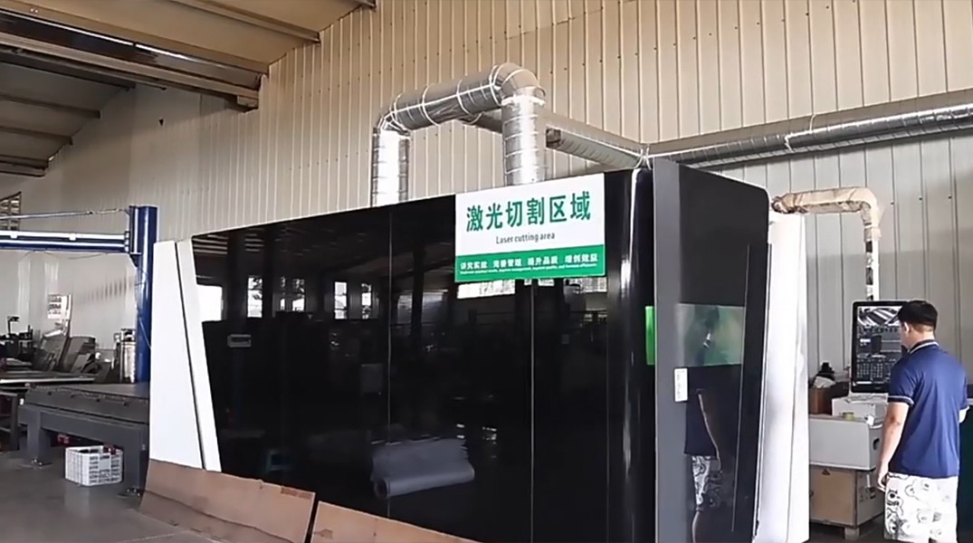
    Laser cutting vs punching - 12,000 W fiber laser cutting cell at XCWY
    The 12,000 W fiber laser cutting cell at XCWY

    How each process removes material

    Fiber laser cutting

    A focused laser beam melts and vaporises a narrow line of material, and an assist gas blows the melt out of the kerf. Oxygen is used on carbon steel for speed, nitrogen on stainless and aluminium for a bright, oxide-free edge. There is no contact and no tool wear, so the process cuts any profile the CAM software can draw. Our 12,000 W fiber laser cuts carbon steel up to 25 mm.

    Punching

    A punch and die shear the material mechanically. On a turret or servo punch press, a library of tools sits in a magazine and the sheet is indexed under them. Round holes, slots and standard shapes are produced by a single hit; non-standard profiles are nibbled from overlapping hits, which is slower and leaves a stepped edge. Punching can also form features — louvres, countersinks, extruded threads, embosses — that a laser cannot produce at all.

    Waterjet

    A high-pressure stream of water carrying abrasive garnet erodes the material. Because this is cold cutting, there is no heat-affected zone, no thermal distortion and no change to the material’s temper. As a result, waterjet cuts almost anything, including titanium, composites, glass, stone and thick plate. However, it is also the slowest of the four, and the abrasive is a consumable cost.

    Plasma

    An ionised gas arc melts the material and blows it away. Plasma is fast and inexpensive on thick conductive plate, but the kerf is wide, the heat-affected zone is substantial and the edge typically has bevel and dross. It is a structural-steel process, not a precision process.

    Laser cutting vs punching: the real trade-off

    The two processes compete directly on thin sheet, so it is worth separating the arguments.

    Laser advantages: no tooling cost or lead time, arbitrary contours and lettering, tight nesting because parts can be placed close together, excellent edge quality on the first pass, and no setup penalty for changing the design between batches. For prototypes and design iterations, laser wins outright — there is nothing to buy before cutting.

    Punching advantages: very fast on repetitive standard features, ability to form as well as cut, lower running cost per hit on thin material, and no heat input at all. If a panel has three hundred identical ventilation holes, a punch will finish it while the laser is still tracing outlines.

    In practice the strongest answer to laser cutting vs punching is often “both”. Punch the repetitive standard features and forms, laser the complex outer profile, and nest the work accordingly. The combined route is normal in high-mix sheet metal production and is one reason it pays to work with a shop that runs a full fabrication chain rather than a single machine.

    Full comparison table

    Attribute Fiber laser Punching Waterjet Plasma
    Typical tolerance ±0.05 – 0.15 mm ±0.10 – 0.20 mm ±0.08 – 0.25 mm ±0.5 – 1.5 mm
    Practical thickness (steel) 0.5 – 25 mm 0.5 – 6 mm Up to 150 mm+ 3 – 50 mm+
    Kerf width 0.2 – 0.4 mm No kerf (shear) 0.8 – 1.2 mm 2 – 4 mm
    Heat-affected zone 0.1 – 0.3 mm None None 0.5 – 3 mm
    Edge quality Clean, minimal burr Slight burr, roll-over edge Matte, taper on thick plate Dross and bevel common
    Tooling required None Punch and die per shape None None
    Can form features No Yes — louvres, embosses, extrusions No No
    Non-metals No No Yes No
    Reflective metals Yes, slower Yes Yes Yes
    Relative speed, 3 mm steel Fast Very fast on standard holes Slow Fast
    Best-fit application General sheet metal, brackets, enclosures High-volume repetitive panels Heat-sensitive alloys, thick or exotic material Heavy structural plate

    Material compatibility

    Fiber lasers handle reflective metals such as copper and brass, which older CO₂ systems struggled with, though feed rates are slower and nitrogen assist is used to keep the edge clean. Aluminium cuts well but leaves a slightly heavier burr as thickness rises. Stainless cut with nitrogen produces a bright edge that needs no descaling before welding or finishing.

    Waterjet is the only one of the four that cuts non-conductive and non-metallic materials, and the only one that leaves the material’s heat treatment completely untouched. That matters for hardened tool steel, some aerospace alloys and anything where a heat-affected zone would compromise fatigue performance. Plasma requires an electrically conductive workpiece by definition.

    Galvanized and pre-coated sheet can be laser cut, but the coating burns back a small amount at the edge, typically about a millimetre. It is cosmetic rather than structural, and edge protection can be applied afterwards. Grade-by-grade behaviour is summarised in our material reference.

    Laser cutting vs punching: cost behaviour across volume

    Cutting cost has two components: setup and run. Laser has almost no setup — load the DXF, load the sheet, cut — so its cost per part is nearly flat from one piece to ten thousand. Punching carries a tooling cost that must be bought once and a setup that must be loaded, but its per-hit run cost on thin material is very low, so the curve falls steeply with volume.

    The crossover therefore depends on feature repetition more than part count. A hundred parts with unusual contours favour laser. Ten thousand parts with the same eight standard holes favour punching. Waterjet almost never wins on cost for standard sheet steel — it wins when nothing else can do the job. Plasma wins on thick plate where the tolerance requirement is genuinely loose.

    Secondary operations to budget for

    • Deburring. Laser edges on thin material are often acceptable as cut; thicker sections and punched parts usually need deburring, particularly if the part will be handled or painted. Cut-edge quality classes for thermal cutting are defined in ISO 9013, which is a useful reference when specifying an acceptable edge.
    • Descaling. Oxygen-cut carbon steel carries a light oxide film that must be removed before painting or powder coating.
    • Taper correction. Waterjet leaves a slight taper on thick sections unless dynamic head compensation is used.
    • Dross removal. Plasma cuts frequently require grinding, which erodes the process’s apparent cost advantage.
    • Flat pattern accuracy. If the part will be bent afterwards, the flat pattern must use the correct K-factor for the material. Cutting a perfect blank from the wrong flat pattern produces a perfectly wrong part — a check worth doing before bending.

    Preparing files that quote accurately

    Send a DXF drawn 1:1 in millimetres, with cut geometry on a single layer and closed polylines for every internal cutout. Remove title blocks, dimensions and construction lines — CAM reads cut paths, and stray geometry gets cut unless someone notices it first. Provide a dimensioned PDF alongside the DXF so critical dimensions and material grade are unambiguous.

    Two design rules save the most money. Keep minimum hole diameter at or above material thickness, since smaller holes degrade in quality and may need secondary drilling. And keep at least one material thickness of space between adjacent cuts and between a cut and a bend line, so the part does not distort during cutting or forming.

    Frequently Asked Questions

    Is laser cutting more accurate than punching?

    Yes, typically. Fiber laser holds around ±0.05 to ±0.15 mm on sheet, while punching is usually ±0.10 to ±0.20 mm because of tool clearance and sheet indexing. The gap narrows on simple parts with few features and widens on complex contoured profiles.

    When should I choose punching over laser cutting?

    Choose punching when the same standard features repeat many times across a high-volume part, or when you need formed features such as louvres, countersinks or extruded threads that a laser cannot produce. Punching also avoids any heat input entirely. For one-offs, prototypes or arbitrary contours, laser is the better choice.

    What thickness can a 12,000 W fiber laser cut?

    Our fiber laser cuts carbon steel up to 25 mm. Stainless and aluminium cut to lower maximum thicknesses than carbon steel because they are processed with nitrogen assist. As thickness approaches the maximum, feed rate drops and per-part cost rises, so the most economical work sits well below the limit.

    Does laser cutting distort thin sheet metal?

    Minor distortion can occur on very thin or large parts because of localised heat input, but the heat-affected zone is small at roughly 0.1 to 0.3 mm. Distortion is controlled through cut sequencing, micro-joints and appropriate nesting. If a part cannot tolerate any thermal input at all, waterjet is the correct alternative.

    Is waterjet worth the extra cost for standard steel parts?

    Usually not. For standard carbon or stainless sheet, laser is faster and cheaper with comparable or better tolerance. Waterjet is justified when the material is heat sensitive, non-metallic, extremely thick, or when the part must retain its original temper exactly.

    Can several cutting processes be used on one part?

    Yes, and it is often the cheapest route. A typical combination punches repetitive holes and formed features, then lasers the complex outer profile. Combining processes is standard practice in high-mix sheet metal work and requires a shop that runs both.

    Send a DXF and we will tell you which process fits

    If you are unsure which cutting route your part should take, the quickest way to settle it is to have an engineer look at the geometry and the volume together. We return a quotation within 3 business hours, with free design-for-manufacture feedback on hole sizes, edge conditions and flat pattern accuracy. Send your DXF to xcwystamping@xcwybj.com or use the quote request form.

  • 304 vs 316 vs 316L Stainless Steel: Choosing the Right Grade for Fabricated Parts

    The practical answer to 304 vs 316 stainless steel is a single question: will the part meet chlorides? Salt spray, seawater, de-icing salt, chlorinated cleaning agents, brine, sweat or coastal air all attack the passive layer that protects stainless. 316 contains roughly 2 to 3 percent molybdenum, and molybdenum is what resists that specific attack. Where chlorides are absent, 304 performs essentially as well and costs less.

    316L is not a third corrosion grade so much as a welding grade. It is 316 with the carbon capped at about 0.03 percent, which prevents chromium carbides from forming at grain boundaries during welding. That precipitation, known as sensitisation, strips chromium from the surrounding metal and leaves the heat-affected zone vulnerable to intergranular corrosion. If your part is welded and will live in a corrosive environment, specify 316L rather than 316.

    Everything else — formability, machinability, appearance, hygiene, strength — is close enough between the grades that it rarely decides the choice on its own. What follows is the detail behind that summary.

    304 vs 316 stainless steel drawn and polished parts produced at XCWY
    Drawn and polished stainless parts produced at XCWY

    304 vs 316 stainless steel: composition and why molybdenum matters

    All three grades are austenitic stainless steels, non-magnetic in the annealed condition, and all rely on a chromium oxide passive film for corrosion resistance. The difference is what happens when that film is locally broken.

    Property 304 / 304L 316 316L
    Chromium 18.0 – 20.0% 16.0 – 18.0% 16.0 – 18.0%
    Nickel 8.0 – 10.5% 10.0 – 14.0% 10.0 – 14.0%
    Molybdenum 2.0 – 3.0% 2.0 – 3.0%
    Maximum carbon 0.08% (304L: 0.03%) 0.08% 0.03%
    Approximate PREN 18 – 20 24 – 26 24 – 26
    Tensile strength, annealed ≥ 515 MPa ≥ 515 MPa ≥ 485 MPa
    Yield strength, annealed ≥ 205 MPa ≥ 205 MPa ≥ 170 MPa
    Elongation ≥ 40% ≥ 40% ≥ 40%
    Chloride resistance Moderate Good Good
    Post-weld corrosion risk Higher in 304 Higher than 316L Lowest
    Relative cost Baseline Typically higher Typically higher

    PREN — the pitting resistance equivalent number, calculated as %Cr + 3.3 × %Mo + 16 × %N — is a convenient single figure for comparing pitting resistance. It is a ranking tool, not a design limit: a higher PREN means better resistance to chloride pitting, but it does not tell you the part will survive a specific environment. Use it to compare candidates, then validate against the actual service condition.

    Pitting and crevice corrosion in practice

    Chloride attack on stainless is rarely uniform. It is localised, and that is what makes it dangerous — a pit can perforate a wall while the surrounding surface still looks perfect.

    Pitting

    Chloride ions penetrate the passive film at a weak point, and a small anodic site develops that keeps dissolving. Higher temperature, higher chloride concentration and stagnant conditions all accelerate it. 304 is noticeably more susceptible than 316 in this regard.

    Crevice corrosion

    The same mechanism, concentrated in a gap where the electrolyte cannot exchange: under a gasket, in an overlapped joint, beneath a washer, in an unfinished weld root. Crevice attack begins at lower chloride levels than open-surface pitting, which is why joint design matters as much as grade selection. Continuous welds instead of intermittent ones, full penetration rather than lap joints, and radiused internal corners all reduce crevice risk. If your design is full of crevices, upgrading from 304 to 316 buys you less than fixing the geometry.

    Why 316L exists: welding and sensitisation

    When austenitic stainless is held between roughly 450 °C and 850 °C — which every weld’s heat-affected zone passes through — carbon migrates to grain boundaries and combines with chromium to form chromium carbides. The metal immediately beside those carbides is now chromium-depleted and no longer properly stainless. Corrosion then follows the grain boundaries, and a weld that looks sound can fail from within.

    Capping carbon at 0.03 percent removes most of the available carbon and largely prevents the reaction. That is the whole purpose of the L grades. Practical guidance:

    • Welded assembly plus corrosive service: specify 316L.
    • Welded assembly in a benign indoor environment: 304 is usually acceptable, 304L if section thickness is significant.
    • Unwelded parts — stamped, drawn, bent or machined only: the L distinction is largely irrelevant, so choose on chloride exposure alone.

    Post-weld treatment matters just as much as grade. Welding leaves heat tint, and heat tint is a chromium-depleted oxide layer that reduces corrosion resistance wherever it remains. Pickling removes it chemically; passivation then restores the protective film. On welded stainless assemblies we pickle and passivate where the drawing calls for it — but it must be called for, because it is a specified operation, not an automatic one.

    Forming and machining: 304 vs 316 stainless steel in the workshop

    Deep drawing and bending

    Both 304 and 316 draw well, with elongation typically at or above 40 percent in the annealed condition. Austenitic stainless work-hardens strongly, which is an advantage for deep shapes because the material resists localised thinning, and a disadvantage because forming loads rise quickly and deep parts may need interstage annealing.

    316 requires somewhat higher forming loads than 304 and springs back slightly more. For bending, both grades typically need a minimum inside radius of about one material thickness in thinner gauges, rising to around 1.5 times thickness as the sheet gets heavier. Neither grade tolerates sharp bends the way annealed aluminium does. Our deep drawing line runs both grades regularly.

    Machining

    All three grades are gummy, work-harden rapidly under a dull tool and produce stringy chips. The rules are the same across the family: sharp tooling, positive rake, rigid setup, generous coolant, and a consistent feed that keeps the tool cutting beneath the work-hardened layer rather than rubbing on it. 316 is marginally more difficult than 304; the L variants machine much like their parent grades.

    When 304 is genuinely enough

    Over-specification is common, and it costs money on every part for the life of the programme. 304 is normally sufficient for:

    • Indoor equipment housings, panels, enclosures and chassis.
    • Kitchen and food-service equipment that contacts food but is cleaned with conventional non-chloride detergents.
    • Architectural and decorative components away from coastal exposure.
    • Structural brackets, frames and mounting hardware in dry environments.
    • Storage vessels for non-chloride contents.

    Specify 316 or 316L when the part will face:

    • Marine, coastal or offshore exposure.
    • Brine, seawater or chloride-bearing process fluids.
    • Chlorinated or halide-based cleaning and sterilisation chemicals.
    • Pharmaceutical, laboratory or medical processing environments.
    • De-icing salt exposure on outdoor or transport equipment.
    • Elevated-temperature service in the presence of chlorides.

    A useful discipline: write the actual service environment on the drawing rather than only the grade. If the drawing says “316L, marine splash zone, chlorinated wash-down”, a supplier can flag when the design’s crevices matter more than the grade. If it says only “stainless”, the review cannot happen. The same principle applies to food equipment parts, where cleaning chemistry frequently drives the grade decision more than the food contact itself.

    Certification and traceability

    For any part where grade matters, ask for EN 10204 3.1 mill test certificates. A 3.1 certificate reports chemical composition and mechanical properties traceable to the mill heat number, issued by the manufacturer’s authorised inspection representative — which means the grade is documented rather than asserted. We supply them on request for every material we process.

    Composition and mechanical property limits for these grades are set by ASTM A240. Material substitution is a real risk in low-cost sourcing, and 304 supplied against a 316 order will pass a visual inspection and most simple tests. Traceability documentation, backed by a quality system, is the practical defence. Ours runs under ISO 9001:2015, registration 34025Q30296R0S, which can be verified independently at cnca.gov.cn.

    Frequently Asked Questions

    What is the main difference between 304 vs 316 stainless steel?

    316 contains 2 to 3 percent molybdenum, which substantially improves resistance to chloride pitting and crevice corrosion; 304 contains none. 304 has slightly higher chromium, 316 has more nickel. In chloride-free environments the two perform similarly, which is why 304 remains the correct choice for most indoor applications.

    Is 316L stronger than 316?

    No, 316L is slightly weaker in the annealed condition, with typical minimum yield around 170 MPa against 205 MPa for 316, because the lower carbon content reduces solid-solution strengthening. The difference rarely matters in sheet metal fabrication. 316L is chosen for weldability and post-weld corrosion resistance, not strength.

    Do I need 316L instead of 316 for a welded part?

    Yes, if the welded part will see a corrosive environment. The low carbon content prevents chromium carbide precipitation in the heat-affected zone, which is what causes intergranular corrosion after welding. For welded parts in dry indoor service, standard 316 or even 304 is generally acceptable.

    How much more does 316 cost than 304?

    316 typically costs more than 304 because of the molybdenum content and higher nickel, and the gap moves with nickel and molybdenum commodity prices rather than staying fixed. Because the premium is ongoing across every part produced, over-specifying the grade is a recurring cost rather than a one-off. Ask for both grades to be quoted if the environment is borderline.

    Can 304 and 316 be deep drawn?

    Yes, both draw well, with elongation typically at or above 40 percent annealed and strong work-hardening that helps resist localised thinning. 316 needs somewhat higher forming loads and shows slightly more springback. Deep parts in either grade may require interstage annealing between redraw operations.

    Does stainless steel need passivation after fabrication?

    It is strongly recommended after welding, grinding or machining, because those operations leave heat tint, embedded iron particles or a disturbed surface that reduces corrosion resistance. Pickling removes heat tint chemically and passivation restores the chromium oxide film. Specify it explicitly on the drawing, since it is a defined operation rather than an automatic step.

    Send the drawing with the service environment noted

    Grade selection is much easier to get right when the supplier knows what the part will actually face. Send your drawing along with the operating environment, cleaning regime and any documentation requirements, and an engineer will confirm the grade, flag any crevice-prone geometry and return a quotation within 3 business hours. Email xcwystamping@xcwybj.com or use the quote request form.

  • Deep Drawing vs Metal Stamping: Which Process Fits Your Part?

    The short answer to deep drawing vs metal stamping: choose deep drawing when your part is a seamless hollow shape whose depth is significant relative to its opening — a cup, a can, a sensor housing, a one-piece enclosure body. Choose metal stamping when your part is essentially flat, shallow, or defined by cut features and bends — a bracket, a clip, a contact, a cover panel. The dividing question is not “how complex is it” but “does the material need to flow into a new three-dimensional volume, or only be cut and bent?”

    That distinction matters because the two processes fail in completely different ways. Stamping problems are usually about springback, burrs and feature position. Drawing problems are about wall thinning, wrinkling and tearing — the material physically running out of ductility. A supplier who is good at one is not automatically good at the other, which is exactly why the deep drawing vs metal stamping decision usually gets made too late, after tooling is already being cut.

    This guide sets out how to make the call early, using geometry, volume and tolerance rather than guesswork.

    Deep drawing vs metal stamping - multi-stage deep drawing line at the XCWY plant
    Multi-stage deep drawing at the XCWY plant, Nanpi, Hebei

    What each process actually does to the metal

    Metal stamping

    Stamping covers a family of operations performed on a press: blanking, piercing, notching, coining, embossing, forming and shallow bending. The blank is cut from strip or coil and the geometry is created by shearing and localised bending. Material thickness stays broadly constant — the sheet is cut and folded, not stretched into a new shape.

    Because the deformation is localised, stamping runs fast, holds tight positional tolerances, and tolerates a wide range of materials. Typical production tolerance for a well-toleranced stamped feature is around ±0.05 mm at XCWY, with press capacity from 25 to 400 tons covering everything from small contacts to heavy structural stampings.

    Deep drawing

    Deep drawing is a stretching and flow process. A blank is clamped by a blank holder and a punch pushes it through a die, drawing the flange material inward to form a wall. The metal genuinely changes shape in three dimensions: the flange gets pulled in, the wall thins, and the corner radius carries the highest strain.

    A part is generally described as “deep drawn” rather than merely “formed” once the depth exceeds roughly half the diameter. Beyond that point, a single stroke will not do it and the part needs redraw stages. Our deep drawing line runs multi-stage forming with typical tolerances around ±0.10 mm — looser than stamping, and that gap is a direct consequence of the physics, not of machine quality.

    Geometry decides first: the draw ratio test

    Before comparing cost, test the geometry. The limiting draw ratio (LDR) is the maximum ratio of blank diameter to punch diameter that a material can survive in one draw. For most steels and aluminium alloys, a first draw of roughly 1.8 to 2.2 is realistic; austenitic stainless can be pushed harder because of its high work-hardening capacity, while high-strength or low-elongation alloys must be kept lower.

    Two practical consequences follow:

    • Depth-to-diameter drives stage count. A shell 30 mm across and 15 mm deep is usually a single-draw part. The same 30 mm diameter at 60 mm deep needs several redraws, each with its own tooling and setup.
    • Each redraw reduces diameter by a limited percentage. Successive draws are progressively less aggressive than the first, because the metal has already work-hardened. Interstage annealing may be required for deep parts in stainless.

    If the part is shallow, none of this applies and stamping is almost always the cheaper route. If the part is deep, no amount of press tonnage substitutes for correct stage planning.

    Deep drawing vs metal stamping: the decision table

    Criterion Metal stamping Deep drawing
    Typical geometry Flat, shallow-formed, bent, pierced Seamless hollow shells, cups, cans, deep housings
    Depth guideline Depth below roughly 0.5 × width Depth above roughly 0.5 × diameter
    Wall thickness Essentially uniform Thins in the wall, thickest at the flange
    Typical tolerance (XCWY) ±0.05 mm ±0.10 mm
    Dominant failure modes Springback, burr, feature position drift Wrinkling, tearing, earing, excessive thinning
    Tooling complexity Low to high depending on die type High — multi-stage sets, blank holder control
    Cycle speed Fast, especially on progressive tooling Slower, particularly with multiple redraws
    Seams and leak paths Present if assembly is welded None in the drawn body
    Best-fit volume Medium to very high Medium to high — tooling must amortise

    Deep drawing vs metal stamping on tooling cost and volume

    Both processes are tooling-led, but the shape of the investment differs. Stamping tooling scales with the number of operations you combine: a single-stage blanking die is modest, a compound die more, a progressive die significantly more because every station must be built and timed together. The payoff is cycle rate — a progressive die produces a finished part per stroke.

    Drawing tooling scales with the number of stages the draw ratio forces on you. A single-draw part can be surprisingly economical. A four-stage part carries four punch-and-die sets plus trim tooling, and that cost lands whether you order 5,000 pieces or 500,000.

    The practical implication for the deep drawing vs metal stamping trade-off is this: a shallow part that could be drawn will nearly always be cheaper stamped, but a deep part that someone tries to fabricate from cut-and-welded panels will accumulate labour on every single piece. Tooling is a fixed cost; welding and grinding are recurring costs. Volume decides which one hurts more.

    When a welded assembly beats a drawn part

    • Annual volumes too low to amortise multi-stage draw tooling.
    • Geometry outside drawing limits — very large, very deep, or sharply rectangular with tight corner radii.
    • Frequent design revisions, where committing to hard tooling is premature.
    • Parts requiring internal structure or partitions that cannot be formed from one blank.

    When a drawn part beats a welded assembly

    • The part must be leak-tight or pressure-retaining; every weld seam is a potential leak path.
    • Cosmetic appearance matters and you would otherwise pay to grind and polish weld seams.
    • Repeat volumes are stable, so the tooling cost divides down.
    • Consistency matters more than flexibility — a drawn shell repeats identically, whereas welded assemblies carry operator variation and distortion.

    Material behaviour: what draws well and what does not

    Formability is governed mainly by elongation, the strain-hardening exponent and planar anisotropy. Practically:

    • Deep-drawing-quality low carbon steel is the reference material — high elongation, predictable flow.
    • Austenitic stainless 304 draws well and work-hardens strongly, so it tolerates deep shapes but may need interstage annealing; 316/316L behaves similarly with slightly higher forming loads.
    • Aluminium 1050, 3003 and 5052 draw well; 6061-T6 does not — its low ductility in the T6 temper makes it a poor drawing candidate and it also demands generous bend radii.
    • Copper and brass are excellent drawing materials with high ductility.
    • Spring steels and high-strength alloys are stamping materials, not drawing materials.

    Earing — the wavy edge produced at the open end of a drawn part — comes from planar anisotropy in the rolled sheet and is normal. It is dealt with by adding trim allowance, not by pretending it will not occur. Material selection details for both routes are summarised on our materials reference.

    Tolerances: set them where they do work

    The most expensive drawings we see apply one tight tolerance band to every dimension. On a drawn part, the achievable tolerance is not uniform across the geometry: the punch-side internal diameter is the most controlled dimension, the open-end diameter is looser, and wall thickness varies by design because the material thinned to get there.

    Specify tightly where a bearing fits, a seal seats or a mating part locates. Allow general tolerances elsewhere. On stamped parts the same principle applies to hole-to-hole positions versus outline dimensions. Doing this well typically removes more cost than any material substitution, and it is exactly what a design-for-manufacture review is for.

    A practical decision sequence

    1. Measure depth against width or diameter. Below roughly 0.5, plan for stamping.
    2. If deeper, estimate draw stages from the draw ratio and check the material will tolerate them.
    3. Ask whether the part must be leak-tight or seam-free. If yes, weight the answer heavily toward drawing.
    4. Compare tooling investment against per-part labour at your realistic annual volume, not your optimistic one.
    5. Re-check tolerances against function and relax everything that is not functional.
    6. Confirm the supplier runs both processes in-house, so the recommendation is not shaped by what they happen to own.

    That last point is not incidental. A shop with only presses will propose a stamped-and-welded assembly; a shop with only draw tooling will propose a drawn part. Both processes run under one ISO 9001:2015 (ISO 9001) system at our plant, which means the process route can be chosen on engineering merit.

    Frequently Asked Questions

    What is the difference between deep drawing and metal stamping?

    Deep drawing forms a flat blank into a seamless hollow shape by drawing material through a die, while metal stamping cuts and bends sheet without significantly changing wall thickness. Drawing changes the part’s three-dimensional volume; stamping changes its outline and adds bends. The practical divide is part depth relative to width.

    At what depth does a part need deep drawing instead of stamping?

    As a working rule, once depth exceeds about half the part diameter or width, the part moves into deep drawing territory. Below that, a shallow form on a press is usually sufficient and cheaper. The exact threshold depends on material ductility and corner radii.

    Which is cheaper, deep drawing or metal stamping?

    For shallow parts, stamping is almost always cheaper because the tooling is simpler and the cycle is faster. For deep, seamless parts, deep drawing usually wins on total cost because the alternative is a welded assembly that carries labour on every piece. The crossover depends on annual volume and how many draw stages the geometry forces.

    Why do deep drawn parts have thinner walls than the original sheet?

    Thinning is inherent to the process: material is stretched as it flows into the wall, and it is thinnest just above the punch corner radius where strain is highest. Good tooling design controls where thinning occurs rather than eliminating it. If a minimum wall thickness is functionally critical, state it on the drawing so blank thickness can be selected accordingly.

    What tolerance can I expect on a deep drawn part?

    Around ±0.10 mm is a realistic production tolerance for our drawn parts, compared with roughly ±0.05 mm for stamped features. Tolerance is not uniform across a drawn geometry — the punch-side diameter is the best controlled, the open end the least. Secondary machining can tighten a specific feature where function requires it.

    Can both processes be combined on the same part?

    Yes, and it is common. A shell can be drawn, then pierced, trimmed, embossed or coined on a press, and finished with hardware insertion or welding for features that cannot be formed. Combining routes is usually how the cheapest overall part is produced.

    Send the drawing and we will tell you which route fits

    If you are undecided between the two processes, the fastest way to resolve it is to have an engineer look at the actual geometry. We return a quotation within 3 business hours, together with free design-for-manufacture feedback covering draw ratio, stage count and any tolerances that are adding cost without adding function. Send your drawing to xcwystamping@xcwybj.com or use the quote request form.