 LOADING
LOADING
LOADING
Prefer to send a drawing? Use the full RFQ form, email xcwystamping@xcwybj.com or message WhatsApp.
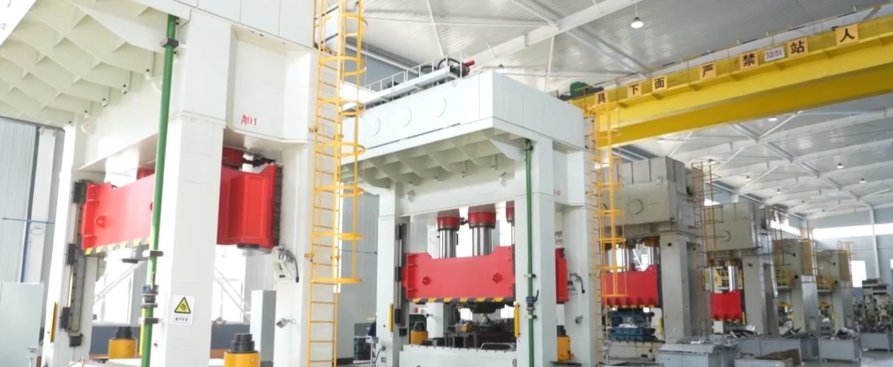
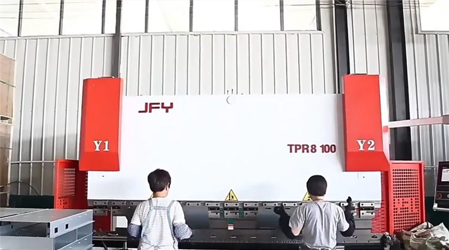
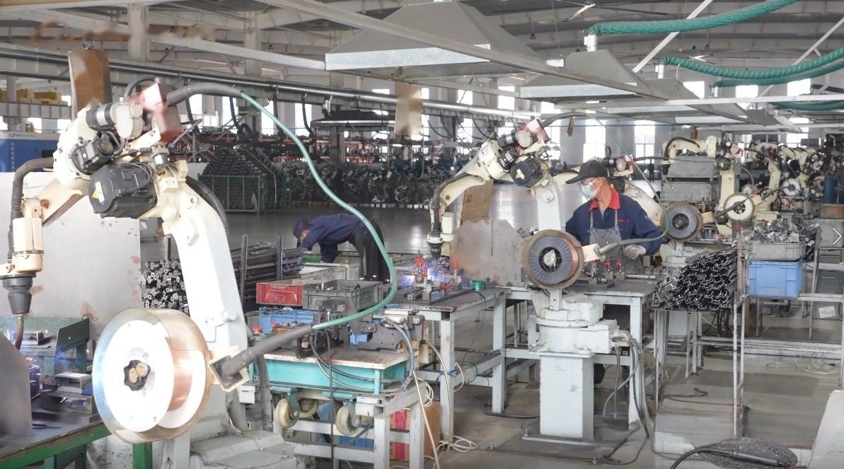
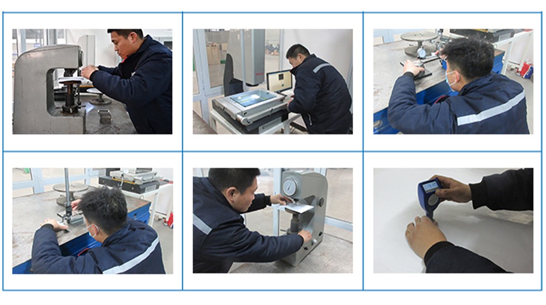
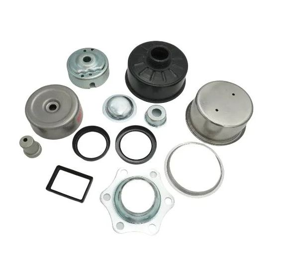
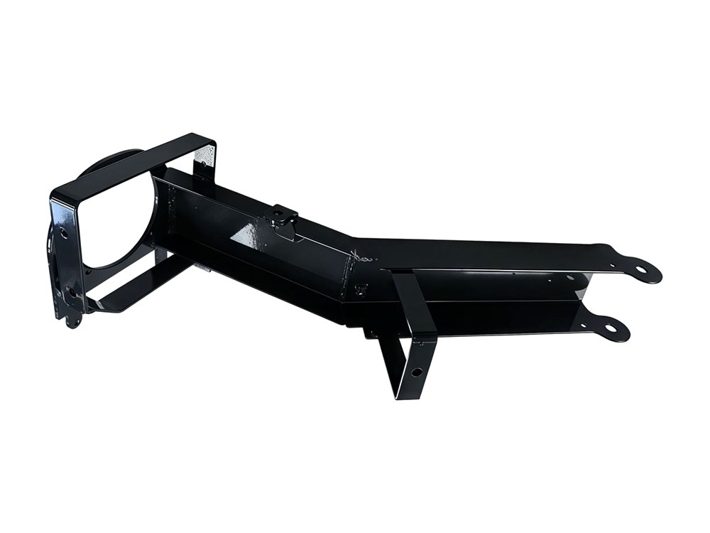
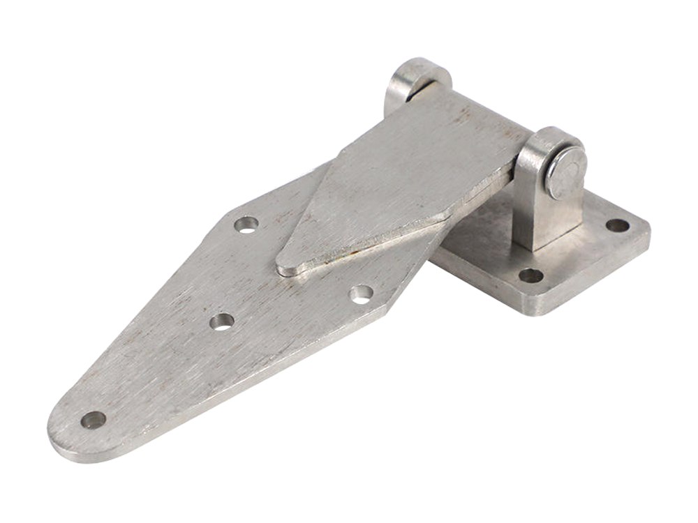
All images below are existing XCWY assets from the factory, production equipment, quality areas or representative custom parts.
Include material, thickness, quantity, critical dimensions, finish and target date. We will review the manufacturing route before quoting.
CNC bending in China · 3,200 mm capacity · since 1998
Most parts that do not fit were not cut wrong — they were unfolded wrong. We develop the flat pattern against the tooling that will actually form your part, then plan a bend sequence the press brake can physically reach.
Bending sits in the middle of a part's life — after cutting, before welding and finishing. Because all of those happen here, the bend sequence is planned around the operations either side of it rather than in isolation.
Four of these five stages happen before the machine is switched on. That is deliberate: a bend cannot be un-bent.
We check flange lengths, hole positions relative to bends, and whether every bend can be reached without the part colliding with the machine.
The flat is developed from your 3D model using the K-factor for the actual material and the tooling we will use, not a generic value.
The order of bends is planned so each one stays reachable. Getting this wrong is why some parts cannot be completed at all.
The first part is measured for angle and dimension, and the programme is corrected for springback before the batch runs.
The rest of the batch runs against the proven setup, then moves to welding, assembly or finishing in the same building.
Almost every fit problem in sheet metal traces back to one of these. All five are visible on the drawing, which is why we look before quoting.
Metal bent to 90° relaxes and opens up slightly when the punch lifts. The amount depends on grade, thickness and radius — stainless springs back noticeably more than mild steel. This is not a fault; it is compensated by overbending, which is set during first-article correction. What it does mean is that the first part off a new setup is measured and adjusted, and any supplier who skips that step is guessing.
A press brake needs enough material either side of the die opening to hold the part down. Below a minimum flange length, the part rocks or slips and the angle cannot be held — the usual guidance is that the flange should be at least around four times material thickness plus the bend radius, though the exact figure depends on the die opening in use. Where a design needs a shorter flange we can sometimes bend long and trim after, but that is a conversation to have before quoting.
Each bend changes the shape the machine has to accommodate for the next one. A four-bend box formed in the wrong order becomes physically impossible to complete at the third bend, because the part will not pass the ram. We plan the sequence at review stage, and where a geometry cannot be bent at all in a single part, we will tell you and suggest splitting it.
K-factor is not a universal constant — it depends on the material, radius and the die used to form the bend. A DXF developed on another shop's press brake will be dimensionally correct for their tooling and slightly wrong on ours. We would rather have your 3D model and develop the flat here. If you send both and they disagree, we will ask which is authoritative rather than pick one.
Sheet is stronger along the rolling direction and more prone to cracking when bent parallel to it. On tight radii in harder grades this decides whether the outer fibre survives. When a part has bends in two directions we plan the blank orientation to protect the more critical one, and say which bend carries the risk.
This review is included with the quotation, whether or not you order. A bend problem found on screen costs an email; found at the machine it costs the blank, the setup and the schedule.
Every bent part starts as a flat blank, and the flat pattern is where the accuracy of the finished part is decided. The bend allowance — the extra material consumed by the bend, which depends on material grade, thickness, the inside radius and the tooling — must be applied correctly or the part comes off the press brake with the holes out of position relative to the flanges. We re-develop the flat from your solid model using the K-factor for the actual material and tooling, and if your supplied DXF disagrees with our development, you are told before anything is cut rather than after.
When the punch releases, the material springs back part of the way toward its original angle. Springback is larger in harder materials — 304 stainless springs back noticeably more than SPCC — and it changes with thickness and bend radius. On our JFY TPR8-100 CNC press brake, compensation is handled by bending past the target angle (overbend) with the exact amount set from the material, and by holding ±0.5° against the print, confirmed at first article. The sequence also matters: bends are ordered so that each flange remains accessible to the tooling, and so that later bends do not deform earlier ones.
Three rules save most bending problems before they happen: keep the inside radius at least equal to material thickness (a sharper radius on stainless invites cracking on the outer fibre, especially across the grain); keep holes and forms at least 2.5× thickness plus radius away from the bend line (inside the deformation zone they stretch into ovals); and respect the minimum flange length for the tooling. Where a design cannot honour these, we say so and propose a relief cut or piercing-after-forming instead of quietly shipping a part that will fail in assembly.
Check these against your folded part before you send it. If a flange is too short to hold or a bend cannot be reached in sequence, we will raise it at quotation rather than at the machine.
| Machine | JFY TPR8-100 CNC press brake | CNC back gauge and angle control |
| Press force | 100 ton | Tonnage rises with thickness and shorter die opening |
| Maximum bend length | 3,200 mm | Single-hit length |
| Material thickness | 0.3 – 6.0 mm | Grade dependent |
| Angle tolerance | ±0.5° | Confirmed at first article |
| Flat pattern | Developed in-house from your 3D model | K-factor matched to our tooling |
| Preceding / following | Laser cutting, welding, finishing | Same work order |
| Quality system | ISO 9001:2015 | Registration 34025Q30296R0S |
CNC sheet metal fabrication depends on more than press capacity. The flat pattern, bend allowance, tooling access, hole-to-bend distance and springback correction must be developed around the actual material and brake tooling before the batch is released.
| Machine | JFY TPR8-100 CNC press brake |
|---|---|
| Capacity | 100 ton press force and 3,200 mm single-hit bend length |
| Angle target | ±0.5° after first-article compensation, subject to material and geometry |
| Materials | SPCC/DC01, Q235, SS304/316L, AL5052, galvanized sheet |
| Control | In-house laser blanking, bend sequence review and first-article measurement |
3,200 mm in a single hit on our JFY TPR8-100. Longer panels have to be split and joined, which introduces a seam — if your design is close to that limit, tell us early and we will look at whether the part can be rearranged to stay within one bend.
±0.5°, confirmed at first article. Tighter angles are sometimes achievable on specific geometries, but we would rather agree a realistic figure than promise one and negotiate at inspection. Mark the angles that are functionally critical and we will confirm those specifically.
No — send the 3D model and we will develop the flat here. That is genuinely better, because the K-factor depends on the tooling doing the bend. If you send a flat pattern developed on another shop's machine it will be slightly wrong on ours, and if you send both and they disagree we will have to stop and ask which one governs.
It depends on material thickness and the die opening in use. As a working rule the flange needs to be at least about four times the material thickness plus the bend radius, otherwise there is not enough material for the tooling to hold and the angle cannot be controlled. Where your design needs shorter, we can sometimes form long and trim afterwards — ask and we will tell you whether that works for your part.
Usually the flat pattern. When a 3D model is unfolded with the wrong K-factor, each bend contributes a small error and they accumulate across the part — enough that holes near the end miss their mates. Send us the model rather than the pattern and this disappears. The second commonest cause is springback that was never compensated at first article.
Yes, though we will want to see the 3D model as well as the blanks so we can check the flat was developed correctly. If it was not, we will tell you before forming rather than after.
MOQ starts at 1 piece, and single pieces can be formed for prototypes. Since bending needs no dedicated tooling, it is an economical way to prove a design before committing to a stamping die.
ISO 9001:2015, registration 34025Q30296R0S, which you are welcome to verify independently. If your programme is governed by an additional standard, name it in your enquiry and we will confirm in writing what we can meet before you place an order.