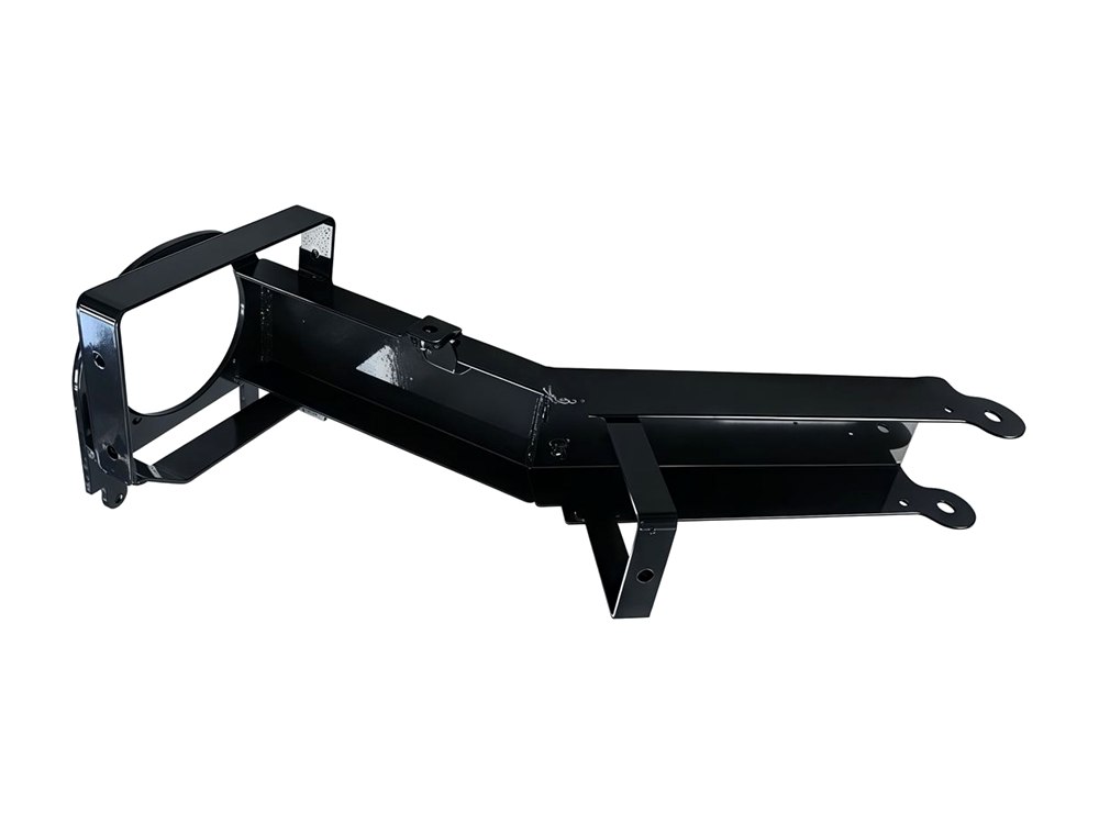
Metal Assembly Design Guide: Joining, Tolerance, and DFM
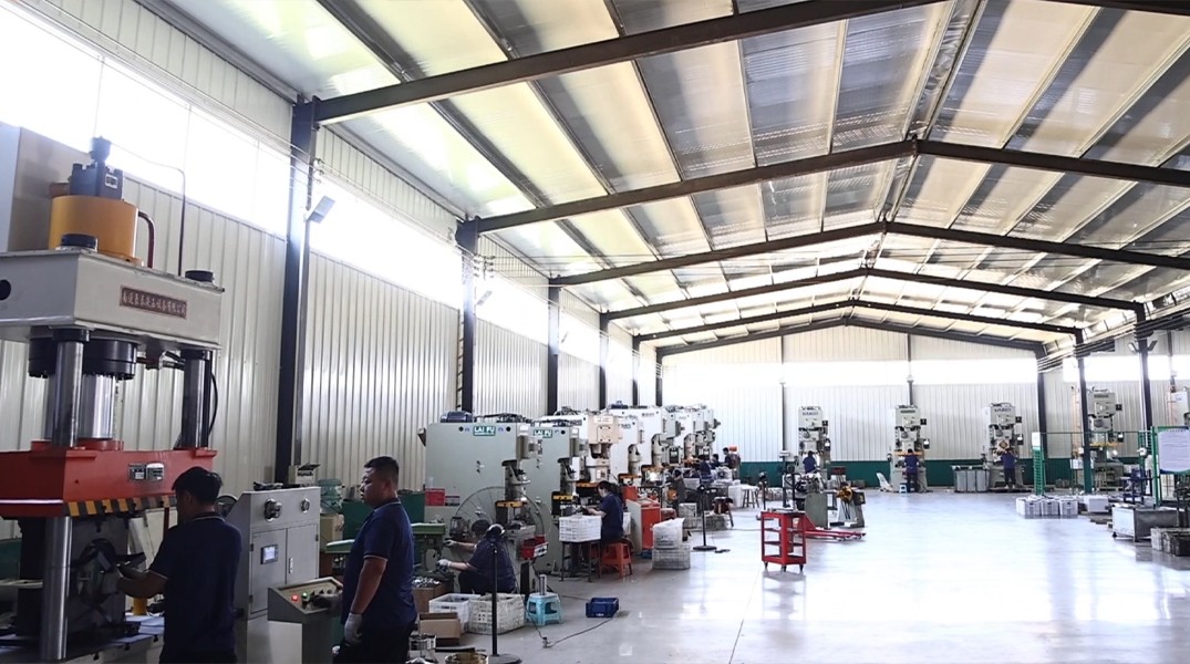
Metal Assembly Design Guide: Joining, Tolerance, and DFM is a practical engineering reference for teams that need manufacturable metal parts without hiding risk behind generic rules. It focuses on assemblies whose final accuracy depends on several cut, formed, machined, welded, and fastened components working together. The guide explains how to translate function into process choices, tolerances, inspection points, and supplier questions. It also shows where prototype evidence should replace assumptions. XCWY has supported metal-part production since 1998 and can combine stamping, deep drawing, laser cutting, bending, five-axis machining, welding, PEM insertion, finishing coordination, and CMM inspection. Available equipment includes 25–400-ton presses, a 12 kW laser, a 3,200 mm press brake, and a DMU38 five-axis center. The operating quality system is ISO 9001:2015, certificate 34025Q30296R0S. Use this metal assembly design guide resource to prepare a clearer RFQ, compare feasible routes, and agree acceptance criteria before material or tooling is committed.
Request a Drawing Review
Attach the drawing, revision, material, quantity, critical tolerances, finish and target date. The inquiry is saved in the site database and emailed to the XCWY team.
Choose a Joining Strategy
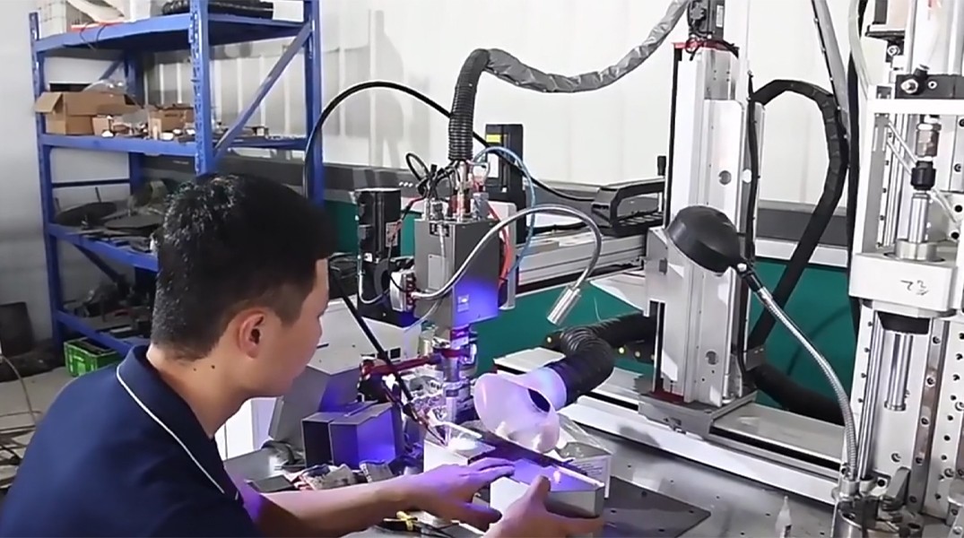
Within metal assembly design guide: joining, tolerance, and dfm, treat choose a joining strategy as a controlled engineering choice rather than a drawing afterthought. Compare TIG and MIG welding for continuous strength, spot welding for overlapped sheet, laser welding for narrow heat input, PEM hardware for serviceable threads, and mechanical fastening for disassembly. Joint selection must consider access from both sides, production volume, corrosion couples, appearance, heat distortion, and whether components need replacement. Do not choose a weld merely because it is easy to symbolize. When documenting choose a joining strategy, separate mandatory functional requirements from preferences, then identify the datums, interfaces, cosmetic zones, load paths, and acceptance evidence relevant to this decision. The drawing, CAD model, material callout, finish note, and revision should give one consistent definition of the choose a joining strategy requirement. Apply tight limits only where choose a joining strategy affects fit, motion, safety, sealing, or interchangeability; a blanket tolerance can add setup and inspection cost without improving performance. If uncertainty remains around choose a joining strategy, approve a representative first article before committing production material or tooling.
Build a Functional Datum Scheme
For metal assembly design guide: joining, tolerance, and dfm, resolve build a functional datum scheme before production data is released. Anchor the assembly to surfaces that actually locate it in the final product. A primary plane, secondary edge, and tertiary feature usually constrain six degrees of freedom more predictably than centerlines inherited from separate components. Dimension hole patterns and interfaces from shared datums; avoid chains across several bent or welded parts because individual variation accumulates at the last connection. When documenting build a functional datum scheme, separate mandatory functional requirements from preferences, then identify the datums, interfaces, cosmetic zones, load paths, and acceptance evidence relevant to this decision. The drawing, CAD model, material callout, finish note, and revision should give one consistent definition of the build a functional datum scheme requirement. Apply tight limits only where build a functional datum scheme affects fit, motion, safety, sealing, or interchangeability; a blanket tolerance can add setup and inspection cost without improving performance. If uncertainty remains around build a functional datum scheme, approve a representative first article before committing production material or tooling.
Design Welds and Heat Paths
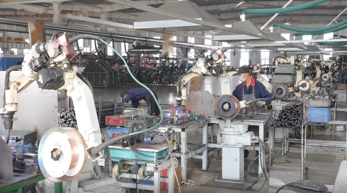
In metal assembly design guide: joining, tolerance, and dfm, a review of design welds and heat paths must connect geometry, material behavior, tooling access, and inspection. Size welds from load and fatigue needs instead of filling every seam. Long uninterrupted beads add heat, cost, and distortion; balanced stitch sequences may be adequate when sealing is not required. Provide torch approach, root condition, gap control, and drainage. Thin stainless parts often benefit from TIG or laser control, whereas longer structural seams may favor MIG productivity. When documenting design welds and heat paths, separate mandatory functional requirements from preferences, then identify the datums, interfaces, cosmetic zones, load paths, and acceptance evidence relevant to this decision. The drawing, CAD model, material callout, finish note, and revision should give one consistent definition of the design welds and heat paths requirement. Apply tight limits only where design welds and heat paths affects fit, motion, safety, sealing, or interchangeability; a blanket tolerance can add setup and inspection cost without improving performance. If uncertainty remains around design welds and heat paths, approve a representative first article before committing production material or tooling.
Manage Tolerance Stack-Up
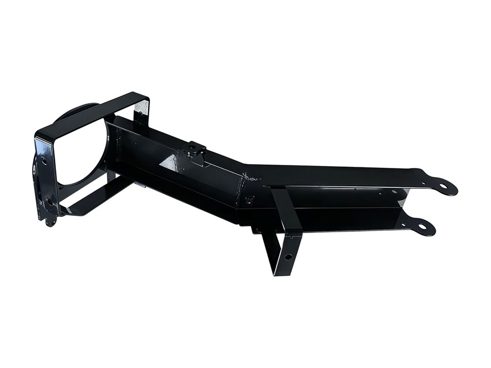
Within metal assembly design guide: joining, tolerance, and dfm, treat manage tolerance stack-up as a controlled engineering choice rather than a drawing afterthought. Create a one-dimensional or geometric stack for every closure, connector, rail, and cover interface. Include cut size, bend location, bend angle, hardware location, fixture repeatability, weld shrinkage, and finish thickness. Statistical methods suit capable repeated production, but worst-case analysis is safer for low-volume interchangeable assemblies or safety-related clearances. Add adjustability only where it has a defined setting method. When documenting manage tolerance stack-up, separate mandatory functional requirements from preferences, then identify the datums, interfaces, cosmetic zones, load paths, and acceptance evidence relevant to this decision. The drawing, CAD model, material callout, finish note, and revision should give one consistent definition of the manage tolerance stack-up requirement. Apply tight limits only where manage tolerance stack-up affects fit, motion, safety, sealing, or interchangeability; a blanket tolerance can add setup and inspection cost without improving performance. If uncertainty remains around manage tolerance stack-up, approve a representative first article before committing production material or tooling.
Plan Fixtures and Assembly Sequence
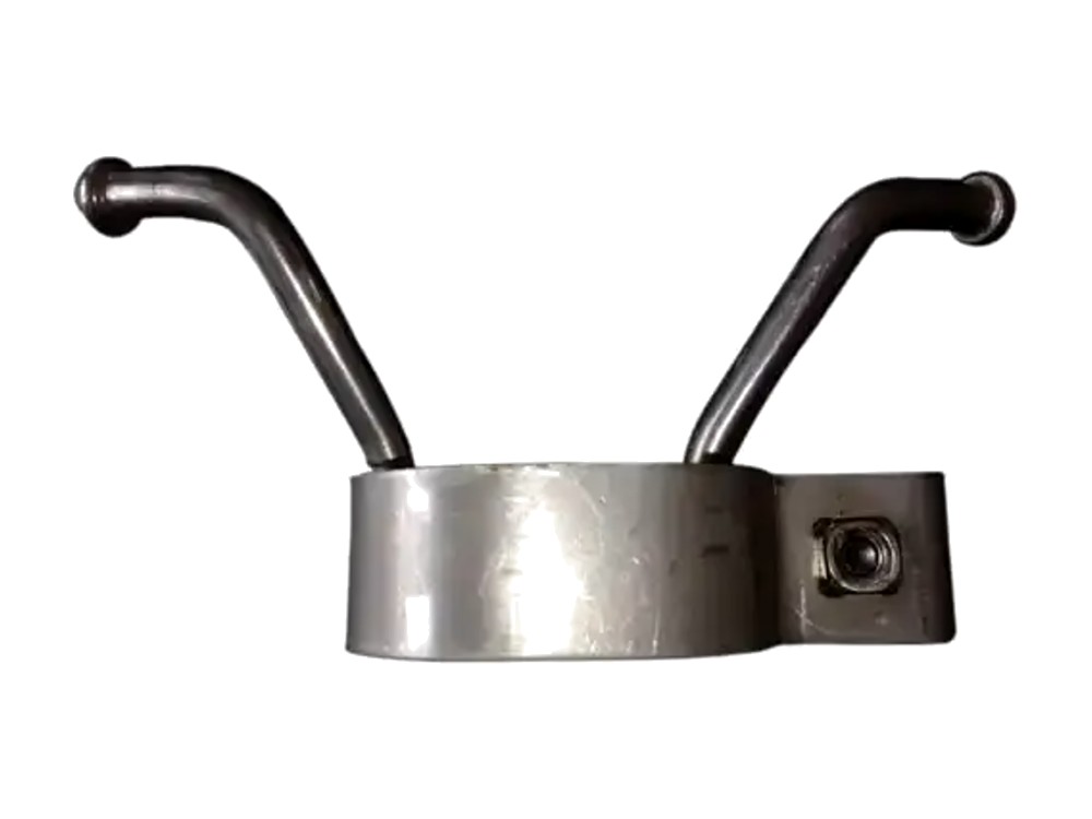
For metal assembly design guide: joining, tolerance, and dfm, resolve plan fixtures and assembly sequence before production data is released. A fixture should locate on stable features, allow clamping without marking cosmetic faces, and leave access for the joining process. Sequence tack welds, full welds, hardware insertion, machining, and coating so an early operation does not block a later one. Temporary tabs, slots, or self-locating joints can reduce operator interpretation, but designers must define whether they remain or are removed. When documenting plan fixtures and assembly sequence, separate mandatory functional requirements from preferences, then identify the datums, interfaces, cosmetic zones, load paths, and acceptance evidence relevant to this decision. The drawing, CAD model, material callout, finish note, and revision should give one consistent definition of the plan fixtures and assembly sequence requirement. Apply tight limits only where plan fixtures and assembly sequence affects fit, motion, safety, sealing, or interchangeability; a blanket tolerance can add setup and inspection cost without improving performance. If uncertainty remains around plan fixtures and assembly sequence, approve a representative first article before committing production material or tooling.
Inspect and Release the Assembly
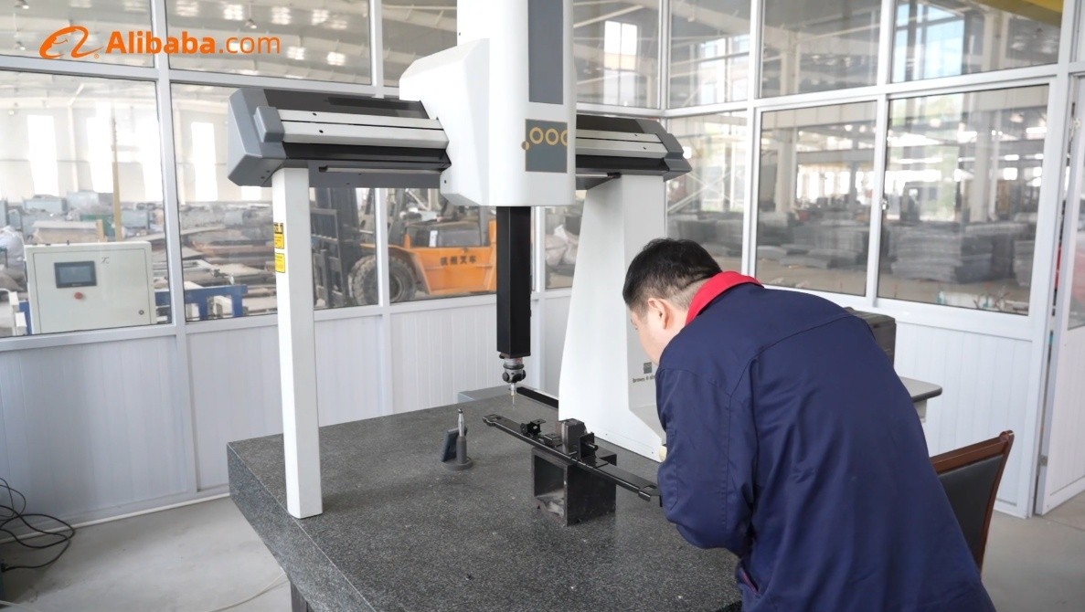
In metal assembly design guide: joining, tolerance, and dfm, a review of inspect and release the assembly must connect geometry, material behavior, tooling access, and inspection. Inspection should verify interfaces, not just isolated component dimensions. Use a CMM for accessible datum relationships, calibrated gauges for production checks, and functional fixtures for complex envelopes. Define flatness after welding and after coating if both matter. A first article should include material identity, purchased hardware, weld condition, finish, and a dimensional report tied to numbered drawing characteristics. When documenting inspect and release the assembly, separate mandatory functional requirements from preferences, then identify the datums, interfaces, cosmetic zones, load paths, and acceptance evidence relevant to this decision. The drawing, CAD model, material callout, finish note, and revision should give one consistent definition of the inspect and release the assembly requirement. Apply tight limits only where inspect and release the assembly affects fit, motion, safety, sealing, or interchangeability; a blanket tolerance can add setup and inspection cost without improving performance. If uncertainty remains around inspect and release the assembly, approve a representative first article before committing production material or tooling.
Engineering Decision Table
| Condition | Recommendation | Why |
|---|---|---|
| Unproven geometry—metal assembly design guide | Run a representative prototype | Evidence reveals springback, distortion, access, and inspection risks in metal assembly design guide. |
| Functional characteristic—metal assembly design guide | Define datum-based measurement | Critical metal assembly design guide controls need unambiguous acceptance evidence. |
| Cosmetic-only feature—metal assembly design guide | Set an appearance-zone limit | A bounded metal assembly design guide standard avoids unnecessary precision cost. |
| Low volume or changing design—metal assembly design guide | Defer dedicated tooling | A flexible metal assembly design guide route preserves revision freedom. |
| Stable repeat demand—metal assembly design guide | Evaluate dedicated tooling or gauges | Upfront metal assembly design guide engineering can reduce cycle time and variation. |
| Approved input changes—metal assembly design guide | Perform a documented delta review | Substitution can change metal assembly design guide dimensions, corrosion, or appearance. |
| Sector certification required—metal assembly design guide | Confirm compliance before sourcing | XCWY does not claim ISO 13485, IATF 16949, AS9100, or UL. |
RFQ and Drawing Checklist
- Define the functional objective and failure modes—metal assembly design guide.
- Attach matching 3D and revision-controlled 2D files—metal assembly design guide.
- State material grade, temper, thickness, and substitution rules—metal assembly design guide.
- Identify datums and critical-to-function dimensions—metal assembly design guide.
- Separate cosmetic surfaces from nonappearance zones—metal assembly design guide.
- Specify edge break, burr direction, and sharp-edge restrictions—metal assembly design guide.
- Call out finish standard, color, gloss, masking, and test method—metal assembly design guide.
- Provide prototype, launch, and expected annual quantities—metal assembly design guide.
- Agree measurement equipment, sampling, and report format—metal assembly design guide.
- Confirm joining hardware, weld symbols, and assembly sequence—metal assembly design guide.
- Review packaging protection for surfaces and formed features—metal assembly design guide.
- Resolve open DFM questions before approving material or tooling—metal assembly design guide.
Manufacturing Evidence — Metal Assembly Design
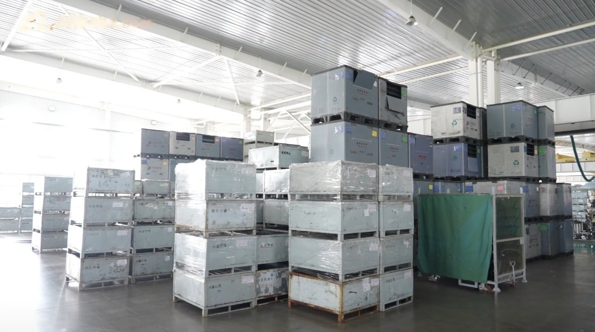
The images below come from the XCWY site asset library and show the plant, equipment, inspection areas and representative parts already published for Metal Assembly Design.
Frequently Asked Questions
When should an engineer request DFM feedback for metal assembly design guide?
Request metal assembly design guide feedback before freezing the drawing and after any material, tolerance, finish, or volume change. An early metal assembly design guide review leaves room to alter geometry before tooling or purchase orders are released.
What files make a metal assembly design guide RFQ technically complete?
For metal assembly design guide, provide matching 3D and controlled 2D data, material grade and temper, quantities, finish, critical dimensions, inspection expectations, and assembly context.
Can XCWY support one metal assembly design guide prototype?
XCWY offers MOQ 1 when the selected metal assembly design guide route is practical. A flexible prototype route may be proposed before production tooling is justified for metal assembly design guide.
How quickly can XCWY quote a metal assembly design guide project?
XCWY targets a metal assembly design guide quotation within three business hours after receiving a complete package. Unclear metal assembly design guide specifications, missing models, or complex tooling require clarification first.
Which quality certification applies to metal assembly design guide?
Work involving metal assembly design guide operates under XCWY’s ISO 9001:2015 system, certificate 34025Q30296R0S. For metal assembly design guide, XCWY does not claim ISO 13485, IATF 16949, AS9100, or UL certification.
What is the most important project-specific check for metal assembly design guide?
Validate the tolerance stack at the final mating interfaces, including weld distortion and finish thickness; a component can pass individually while the assembly still fails to fit.
Related XCWY Capabilities
Get a Manufacturing Review and Quote
Attach the drawing, revision, material, quantity, critical tolerances, finish and target date. The inquiry is saved in the site database and emailed to the XCWY team.