Category: Manufacturing Services

Deep dives into XCWY manufacturing capabilities — stamping, deep drawing, laser cutting, CNC bending, welding, 5-axis machining and surface finishing, with equipment specifications and quality controls.

  • Sheet Metal Fabrication vs CNC Machining: Which Should Make Your Part?

    The sheet metal fabrication vs CNC machining decision follows from one property of the part: is the geometry essentially a folded surface, or is it a solid body with internal features? Sheet metal starts with flat stock and creates shape by cutting and bending it. CNC machining starts with a solid block or bar and creates shape by removing material. Those two starting points lead to completely different cost structures, tolerances and design rules.

    As a working rule, if the part has a roughly constant wall thickness and could be unfolded into a flat pattern, fabricate it. If it has varying thickness, internal pockets, threaded bosses, complex three-dimensional surfaces or tolerances tighter than about ±0.1 mm across the whole part, machine it.

    The interesting cases are the ones in between, where either route is technically possible. Those are usually decided by volume, tolerance on a small number of critical features, and how much material would end up as chips.

    Sheet metal fabrication vs CNC machining - five-axis machining centre at XCWY
    The HDL-OKK DMU38 five-axis machining centre at XCWY

    Sheet metal fabrication vs CNC machining: what each process does

    Sheet metal fabrication

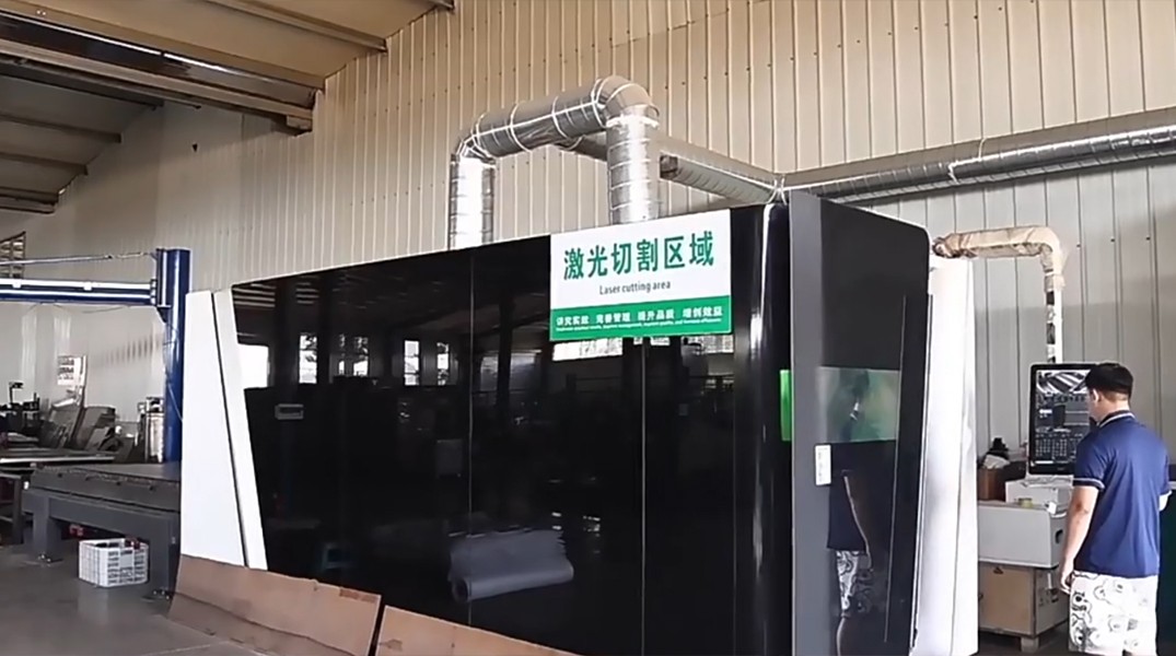
    Flat stock is cut — normally by laser — then bent on a press brake, welded where needed, fitted with hardware and finished. Material thickness stays constant throughout, because the process folds a surface rather than carving a solid.

    The number of operations, rather than material removal, drives the economics. A part with four bends and six holes is cheap; the same part with thirty bends and a welded sub-frame is not. Our fabrication chain runs 0.3 to 6.0 mm sheet, with bends up to 3,200 mm long and bend angle tolerance of ±0.5° as standard.

    CNC machining

    A cutting tool removes material from solid stock under numerical control. Three-axis machining handles prismatic parts requiring multiple setups; simultaneous five-axis machining reaches complex geometry in a single setup, which eliminates the cumulative error that comes from re-fixturing.

    Here, cycle time and the volume of material removed drive the economics. Machining holds far tighter tolerances than fabrication — our HDL-OKK DMU38 five-axis centre works to ±0.005 mm — but every cubic millimetre removed is paid for twice, once as purchased stock and once as machine time.

    Decision table

    Criterion Sheet metal fabrication CNC machining
    Starting material Flat sheet or coil Solid block, plate or bar
    Wall thickness Constant, 0.3 – 6.0 mm typical Variable by design
    Typical tolerance ±0.1 – 0.5 mm; ±0.5° on bends ±0.02 mm standard, ±0.005 mm precision
    Material utilisation High — nesting minimises offcut Low — most of the block becomes chips
    Internal features Limited — no pockets or blind cavities Pockets, bores, threads, undercuts
    Complex 3D surfaces No Yes, especially five-axis
    Large enclosures and panels Well suited Impractical and costly
    Cost at low volume Low — no tooling Moderate — programming and fixturing
    Cost at high volume Falls with batching Falls slowly — cycle time is fixed
    Minimum quantity Prototypes upward Genuinely viable from one piece
    Strength approach Stiffness from geometry — flanges, ribs Strength from solid section
    Weight Light for the volume enclosed Heavier unless material is removed deliberately

    Tolerance: where fabrication genuinely cannot compete

    Fabrication tolerances accumulate. Each bend carries angular variation, and each subsequent bend inherits the position error of the one before it. Across a part with several bends, the tolerance stack-up on a final feature can be substantially larger than any single operation’s tolerance.

    Machining does not accumulate error in the same way, because features are cut from a datum that does not move within a setup. Five-axis machining extends that advantage by reaching multiple faces without re-fixturing.

    The practical consequence is not “machine the whole part”. It is that a critical interface on an otherwise fabricated part can be machined afterwards. A bearing bore, a sealing face, a precisely located mounting pattern — fabricate the body, then machine the one feature that needs to be right. This hybrid is usually far cheaper than machining the entire part from solid, and it is where most of the avoidable cost in this comparison hides.

    Material waste and its real cost

    The difference in material utilisation is larger than most cost models capture. Laser cutting nests parts closely and the shop recycles the skeleton, so utilisation stays high. Machining a bracket from solid can turn most of the purchased block into chips, and on expensive alloys such as 7075 or 316 stainless that waste dominates the part cost.

    Three implications follow:

    • The higher the material cost per kilogram, the more strongly the comparison favours fabrication.
    • As the part’s bounding box grows relative to its finished volume, machining looks progressively worse.
    • Near-net starting stock — plate close to final thickness, or a fabricated blank — recovers much of the difference when machining is unavoidable.

    Sheet metal fabrication vs CNC machining across volume

    Neither process requires hard tooling, which is what distinguishes both from stamping. But their volume curves still differ.

    Fabrication cost falls meaningfully with batch size. Nesting improves, press brake setups amortise across more parts, and handling becomes more efficient. Moving from ten parts to a thousand produces a real per-part reduction.

    Machining cost falls more slowly. Programming and fixturing amortise, and a good programmer can shorten the cycle, but the machine still has to remove the same material from every piece. Beyond a certain volume the curve flattens because cycle time is irreducible.

    This is why machining is excellent for one-off precision parts and progressively less attractive as volume grows, while fabrication improves with volume and eventually gives way to stamping when volumes justify hard tooling. If your quantities are heading into the thousands and the part is a formed sheet component, the comparison to run next is fabrication against stamping, not against machining.

    Design rules that decide the outcome

    Design for fabrication

    • Keep wall thickness constant — that is the process’s defining assumption.
    • Use a consistent bend radius throughout, ideally one that matches standard tooling.
    • Respect minimum flange height, roughly four times material thickness plus the inside radius, or the flange slips into the die.
    • Keep holes at least two material thicknesses from a bend line to avoid distortion.
    • Add stiffening geometry — flanges, ribs, embossments — rather than increasing thickness.
    • Use self-clinching hardware for threads instead of tapping thin sheet.

    Design for machining

    • Internal corner radii should be as large as function allows; sharp internal corners require small tools and long cycles.
    • Limit pocket depth relative to tool diameter — deep narrow pockets need long tools that chatter.
    • Standardise hole sizes to reduce tool changes.
    • Minimise the number of setups; each one adds cost and a tolerance stack.
    • Apply a general tolerance class such as ISO 2768 and avoid tight tolerances on non-functional features, since inspection cost rises with them.
    • Consider whether a thinner near-net starting stock would remove machining time.

    When to combine both

    The lowest-cost answer is frequently a hybrid, and identifying it early is the highest-value part of a design review.

    1. Fabricated body, machined interface. A sheet metal chassis with one machined mounting face where alignment is critical.
    2. Fabricated enclosure, machined inserts. A sheet housing with machined bosses welded or pressed in where threads must carry load.
    3. Machined part, fabricated brackets. A precision core assembly with fabricated mounting hardware around it.
    4. Post-machining after welding. Weld the assembly, then machine the critical features so the final cut removes welding distortion rather than tolerating it.

    That last option is underused. Machining before welding almost always lets the precision feature move; cutting it after welding costs a setup but delivers a part that actually sits within tolerance.

    Frequently Asked Questions

    Which is cheaper, sheet metal fabrication or CNC machining?

    Sheet metal fabrication is usually cheaper for parts that can be made from folded flat stock, because material utilisation is high and cycle times are short. CNC machining wins when the part needs internal features, varying thickness or tolerances tighter than fabrication can hold. The gap widens with expensive alloys, where machining waste dominates cost.

    What tolerance can sheet metal fabrication hold?

    Expect roughly ±0.1 to ±0.5 mm on dimensions and ±0.5° on bend angles as standard, with tighter angle control available on request. Tolerances accumulate across multiple bends, so a feature at the end of a long bend sequence carries more variation than a single operation would suggest. Machine any individual feature that needs to be tighter.

    Can a part be both fabricated and machined?

    Yes, and it is often the cheapest route. A common pattern is to fabricate the body and machine only the one or two features requiring precision, such as a bearing bore or sealing face. Machining after welding also removes distortion that would otherwise put the feature out of tolerance.

    When does CNC machining make sense for low quantities?

    Machining is genuinely viable from a single piece because no tooling is required — only programming and fixturing. That makes it well suited to prototypes, fixtures, one-off precision components and spares. Fabrication is also tooling-free, so for low quantities the choice returns to geometry and tolerance rather than volume.

    Does machining waste much material?

    Yes, often substantially. Machining a part from solid can convert most of the purchased block into chips, whereas laser nesting on sheet keeps utilisation high. On costly alloys such as 7075 aluminium or 316 stainless, this waste can be the largest single element of part cost.

    Which process is better for enclosures?

    Sheet metal fabrication, in almost all cases. Enclosures are thin-walled, large in area and low in structural mass, which is exactly what folding flat stock is good at. Machining an enclosure from solid would remove most of the material and cost far more.

    Send the model and we will recommend a route

    If a part could plausibly go either way, the fastest way to resolve it is to have both processes assessed against the same geometry by people who run both. Send a STEP file or drawing and an engineer will recommend a route, flag any features driving unnecessary cost and return a quotation within 3 business hours. Email xcwystamping@xcwybj.com or use the quote request form.

  • Welded vs Deep Drawn Enclosures: Which Construction Costs Less to Own?

    An enclosure body can be built two ways: cut flat panels and weld them into a box, or draw a single blank into a seamless shell. The welded vs deep drawn enclosures decision is a straight trade between fixed cost and recurring cost. Welding needs little or no tooling but consumes labour on every unit — tacking, welding, grinding, straightening, polishing. Drawing needs real tooling investment but then produces a finished shell in a press cycle with no seams to close and no welds to dress.

    The other half of the decision is functional. A drawn shell has no seams, so it has no leak paths through the body, no weld porosity, no distortion from heat input and no ground-back weld beads to blend. If the enclosure must be sealed, pressure-retaining or cosmetically flawless, that structural difference often decides the matter before cost is even calculated.

    Where drawing loses is geometry and flexibility. Draw ratio limits how deep a shell can be relative to its opening, sharp rectangular corners are difficult, very large enclosures exceed practical press capacity, and any design change means new tooling. This guide sets out where each construction genuinely wins.

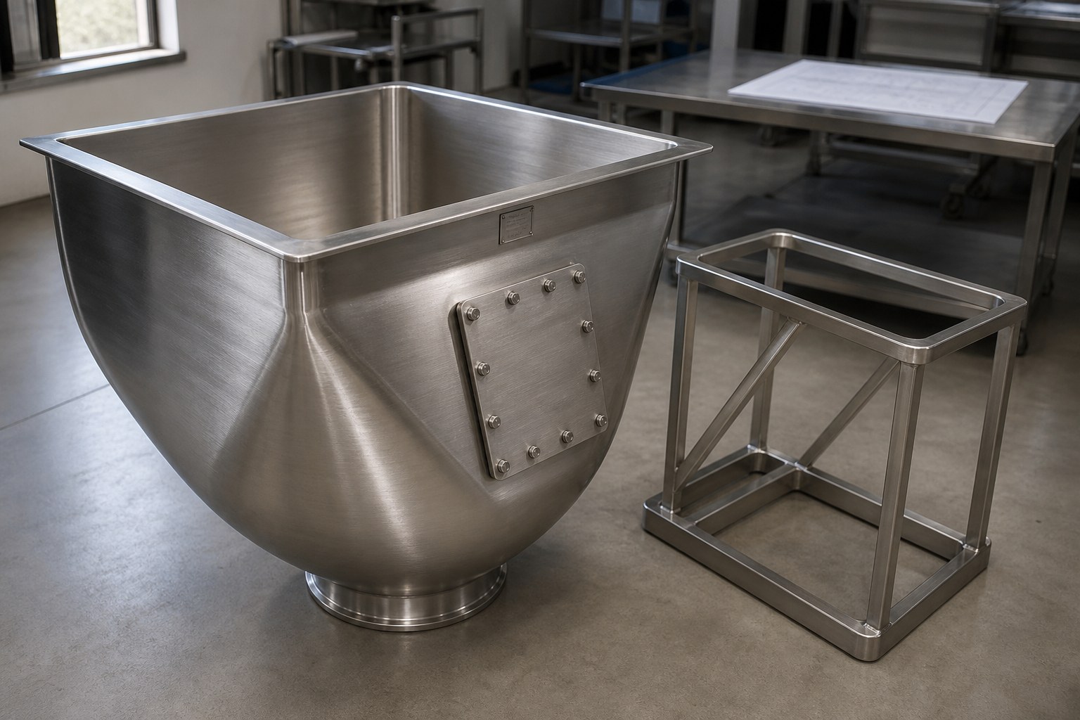
    Welded vs deep drawn enclosures - seamless deep drawn shell from XCWY
    A seamless deep drawn shell, with no weld seams in the body

    How each construction is built

    Welded construction

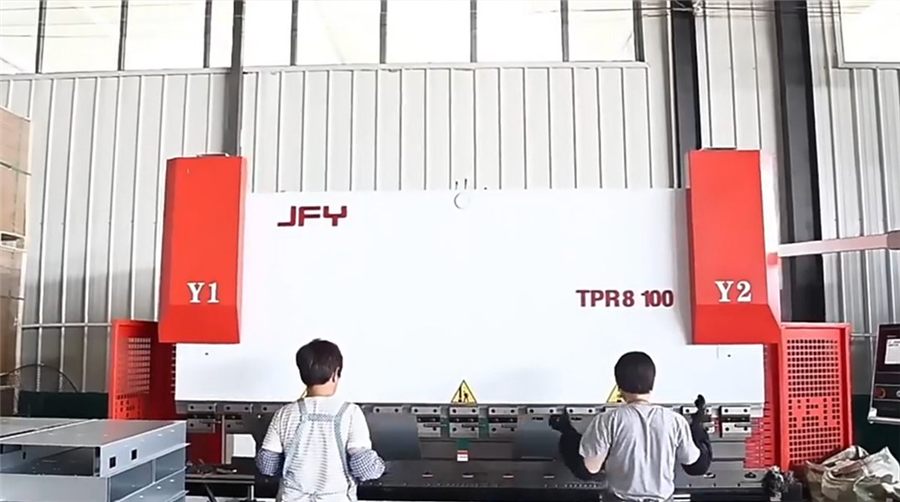
    Panels are cut — usually laser cut — then bent on a press brake, positioned in a fixture, tacked, welded and dressed. Our 3,200 mm press brake forms panels up to that length in a single stroke, and joining runs through laser welding, TIG, MIG or spot welding depending on the material, thickness and the appearance required.

    The strength of this route is that almost any geometry is achievable. Rectangular boxes with sharp corners, enclosures with internal partitions, mounting bosses, cable entries and cut-outs anywhere — all straightforward. It also requires no hard tooling, so the first unit can ship quickly and the design can change between batches.

    The cost, quite literally, is labour. Every seam must be welded and, if the enclosure is visible, ground flush and polished. Heat input distorts panels, so fixturing and weld sequencing matter. On stainless, heat tint must be pickled off and the surface passivated.

    Deep drawn construction

    A blank is clamped and a punch draws it through a die, forming a one-piece shell with a continuous wall and no seams. Depth beyond roughly half the diameter requires successive redraw stages, then the open end is trimmed to length. Our deep drawing line runs multi-stage forming with typical tolerances around ±0.10 mm.

    The advantages follow directly from having no seams: nothing to leak, nothing to grind, nothing to distort, and each unit is identical to the last because the die does not vary the way a welder’s hand does. Corner radii are naturally generous, which is good for sealing and for coating adhesion.

    The limits are equally direct. Tooling must be built and paid for. Draw ratio constrains depth. Sharp rectangular corners fight the process. And a design revision after tooling is cut is expensive.

    Welded vs deep drawn enclosures: sealing settles most cases

    For any enclosure with an IEC 60529 IP rating requirement, count the potential leak paths in each construction.

    In a welded box, every seam is one. A continuous, full-penetration weld properly executed is leak-tight — but “properly executed” is doing real work in that sentence. Porosity, undercut, a stop-start defect or a crater at a corner junction each create a path. Corners where three welds meet are the classic failure point. Leak testing on welded enclosures is therefore not optional for sealed applications; it is part of the process.

    In a drawn shell, the body has no seams at all. The only sealing interfaces are the ones you deliberately designed: the door or lid gasket, and any cable gland or connector penetration. That is a smaller, better-controlled set of variables, and it is why drawn construction is common for sealed instrument housings and sensor bodies.

    Corner geometry reinforces the point. A drawn shell has smooth radiused corners that a gasket can follow continuously. A welded box has a ground weld bead at each corner, and gaskets seal poorly across an uneven bead. Achieving the same sealing reliability in welded construction requires machined sealing faces or a continuous gasket channel — both add cost.

    Comparison table

    Criterion Welded enclosure Deep drawn enclosure
    Tooling investment None or minimal fixturing Significant — multi-stage die set
    Labour per unit High — weld, grind, straighten, polish Low — press cycle plus trim
    Seams in body Multiple None
    Sealing reliability Depends on weld quality; leak test needed Inherent in the body; only designed joints seal
    Geometry freedom Very high — any box, partitions, features Constrained by draw ratio and corner radii
    Size range Up to 3,200 mm panel length Limited by press and die size
    Depth capability Unrestricted Governed by draw ratio and stage count
    Sharp corners Achievable Difficult — radii are inherent
    Distortion risk Present — heat input Minimal — no heat
    Cosmetic finishing Grinding and polishing required Little or none on the body
    Unit-to-unit consistency Operator-dependent Die-controlled, highly repeatable
    Design change cost Low High once tooling exists
    Best-fit volume Low to medium Medium to high, stable

    Welded vs deep drawn enclosures: where the cost actually goes

    Buyers comparing the two routes often compare only the piece price at their current volume and miss the shape of the curve.

    Welded construction has a flat cost curve. The tenth unit costs close to what the thousandth costs, because welding and grinding labour do not scale away. Some efficiency comes from better fixturing and operator familiarity, but the floor is set by the time it physically takes to lay and dress a weld.

    Drawn construction has a steeply falling curve. The tooling is paid once, and after that the marginal cost is a press cycle. As volume rises, the tooling cost divides down until it becomes a rounding error against the labour it eliminated.

    Two costs are routinely underestimated when the two are compared:

    • Weld dressing on cosmetic enclosures. Grinding a weld flush and polishing it to a uniform brushed finish is skilled manual work, and on a visible enclosure it can rival the welding time itself.
    • Rework from distortion. Heat input warps panels. Straightening after welding, or scrapping an assembly that will not sit flat, is a real recurring cost that rarely appears in a piece-price comparison.

    The corollary is that the crossover point is not a fixed volume. It moves with how cosmetic the enclosure is, how many seams it has, and how tight the flatness requirement is. A plain internal chassis crosses over late; a polished stainless housing with a demanding gasket face crosses over early.

    When geometry forces welded construction

    • Enclosures too large for practical die and press capacity.
    • Depth beyond what the draw ratio allows for the material, even across multiple redraws.
    • Sharp rectangular corners that the design cannot compromise on.
    • Internal partitions, shelves or structural ribs that cannot be formed from one blank.
    • Variable-thickness sections, or different materials in different areas.
    • Designs still in revision, where committing to hard tooling would be premature.
    • Volumes too low to amortise the tooling under any reasonable assumption.

    When drawn construction wins clearly

    • The enclosure must be leak-tight, and reliably so across every unit.
    • The body is visible and a seamless appearance is worth paying for.
    • Volumes are stable and repeat over several years.
    • Wall consistency and dimensional repeatability matter more than geometric freedom.
    • Downstream finishing labour is a significant share of current cost.

    A hybrid is often the real answer

    The two routes are not mutually exclusive, and the cheapest enclosure frequently combines them. A drawn shell forms the sealed body while a laser-cut, bent and welded lid, bracket set or mounting frame handles the features that drawing cannot produce. Hardware such as PEM studs, standoffs and earth bosses is pressed in afterwards regardless of which route the body took.

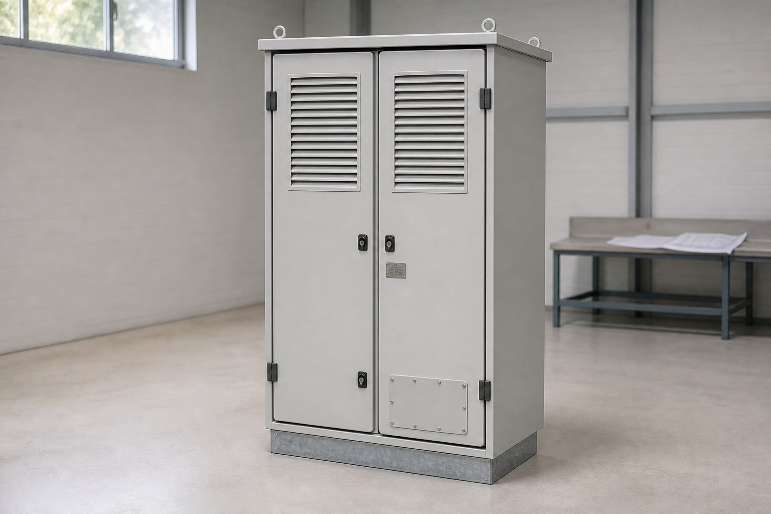
    Deciding this well requires a supplier that runs both processes rather than one. A shop with only press brakes and welders will propose a welded box; a shop with only draw tooling will propose a shell. Both run in our plant under one ISO 9001:2015 system, alongside welding and assembly, which means the route can be chosen on the part rather than on the equipment list. The same reasoning applies across our enclosure work and outdoor telecom cabinets.

    Inspection differences worth planning for

    Welded enclosures need weld inspection: visual examination against acceptance criteria, dye penetrant testing where welds are critical, and leak testing for sealed units. Flatness and squareness need checking after welding because heat input moves things. Each of these is an inspection operation with a cost attached.

    Drawn shells need different checks: wall thickness at the thinnest point, which is typically just above the punch corner radius; dimensional verification of the controlled diameter; and inspection for any drawing defect such as tearing or wrinkling. There is no weld to test, which removes a whole inspection category.

    Both routes pass the same four gates in our plant — incoming material, first article, in-process sampling and final AQL inspection per ISO 2859-1 — but the content of those checks differs by construction, and that difference should be reflected in the drawing’s inspection requirements.

    Frequently Asked Questions

    Are deep drawn enclosures better sealed than welded ones?

    Generally yes, because a drawn shell has no seams in the body and therefore no weld-related leak paths. A properly executed continuous weld can also be leak-tight, but it depends on weld quality across every unit and normally requires leak testing to confirm. Drawn shells also offer radiused corners that gaskets seal against more reliably than a ground weld bead.

    At what volume does deep drawing become cheaper than welding?

    There is no universal figure, because the crossover depends on how much welding and grinding labour the welded version requires and how many draw stages the geometry needs. Cosmetic enclosures with many seams cross over at much lower volumes than plain internal chassis. Compare total cost including finishing labour and rework at your realistic annual volume rather than comparing piece price alone.

    How deep can a drawn enclosure be?

    Depth is governed by the limiting draw ratio of the material and the number of redraw stages, not by a single fixed limit. A first draw typically achieves a depth of roughly half the diameter, with successive redraws going deeper at a reducing rate. Deep parts in stainless may need interstage annealing between draws.

    Can a deep drawn enclosure have sharp corners?

    Not truly sharp ones. Drawing inherently produces radiused corners, and forcing tight radii concentrates strain and causes tearing. If the design requires sharp corners for appearance or fit, welded construction is the appropriate route, or the design should be reviewed to see whether a radius is acceptable.

    Which construction handles design changes better?

    Welded construction, decisively. Changing a cut-out, a dimension or a feature means editing a DXF and adjusting the fixture. On a drawn part, a change to the shell geometry usually requires new tooling. This is why designs that are still evolving should stay welded until they stabilise.

    Can the two constructions be combined in one product?

    Yes, and it is common. A drawn shell forms the sealed body while a fabricated lid, bracket or internal frame provides the features drawing cannot produce. Hardware insertion, finishing and assembly then proceed identically for either route.

    Send the enclosure drawing and the annual volume

    The welded versus drawn question is best answered by looking at the actual geometry alongside the volume, since either input alone gives the wrong answer. Send both and an engineer will assess draw feasibility, estimate stage count, identify the finishing labour in the welded alternative, and return a quotation within 3 business hours. Email xcwystamping@xcwybj.com or use the quote request form.