Laser Cutting Design Guide for Accurate Sheet Metal Parts
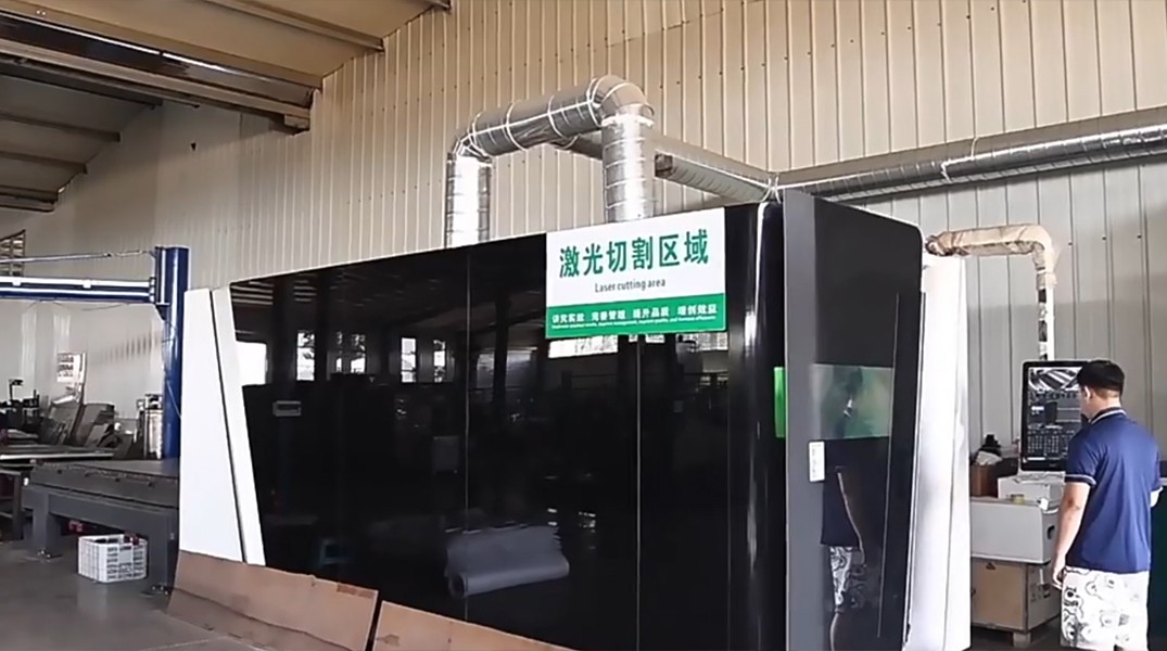
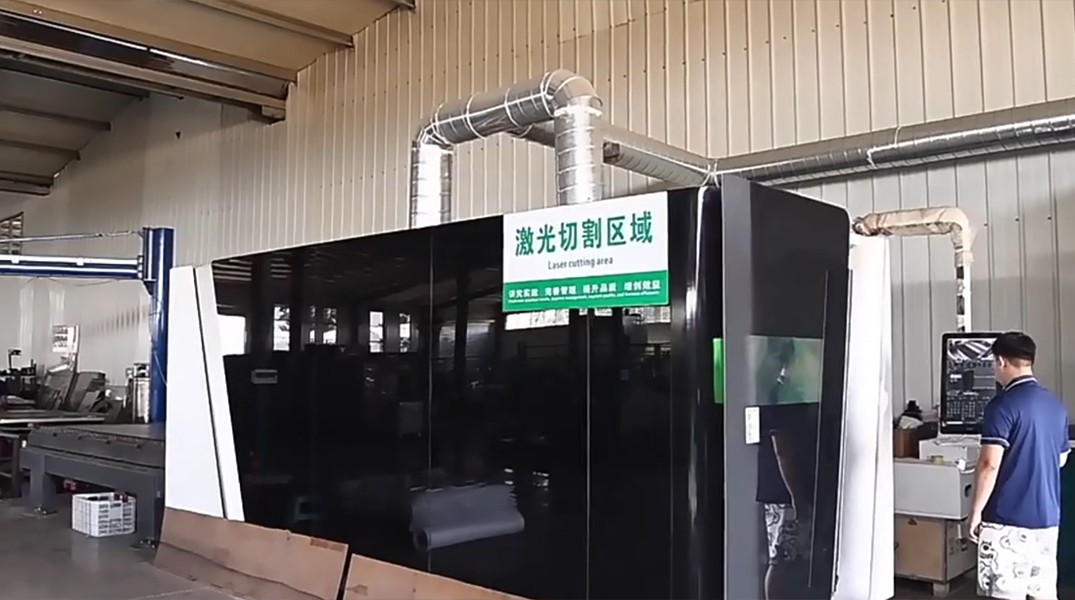
Laser Cutting Design Guide for Accurate Sheet Metal Parts is a practical engineering reference for teams that need manufacturable metal parts without hiding risk behind generic rules. It addresses flat-pattern preparation, feature sizing, kerf, nesting, edge condition, and the limits that change with alloy and thickness. The guide explains how to translate function into process choices, tolerances, inspection points, and supplier questions. It also shows where prototype evidence should replace assumptions. XCWY has supported metal-part production since 1998 and can combine stamping, deep drawing, laser cutting, bending, five-axis machining, welding, PEM insertion, finishing coordination, and CMM inspection. Available equipment includes 25–400-ton presses, a 12 kW laser, a 3,200 mm press brake, and a DMU38 five-axis center. The operating quality system is ISO 9001:2015, certificate 34025Q30296R0S. Use this laser cutting design guide resource to prepare a clearer RFQ, compare feasible routes, and agree acceptance criteria before material or tooling is committed.
Request a Drawing Review
Attach the drawing, revision, material, quantity, critical tolerances, finish and target date. The inquiry is saved in the site database and emailed to the XCWY team.
Match Material and Thickness to Capability
Within laser cutting design guide for accurate sheet metal parts, treat match material and thickness to capability as a controlled engineering choice rather than a drawing afterthought. Confirm alloy, temper, surface film, thickness tolerance, flatness, and reflectivity before nesting. XCWY’s 12 kW laser capacity is stated as carbon steel through 25 mm, stainless steel through 20 mm, aluminum through 12 mm, and copper through 6 mm. These are maximum stated capacities, not promises of identical edge quality, speed, tolerance, or pierce behavior across every grade. When documenting match material and thickness to capability, separate mandatory functional requirements from preferences, then identify the datums, interfaces, cosmetic zones, load paths, and acceptance evidence relevant to this decision. The drawing, CAD model, material callout, finish note, and revision should give one consistent definition of the match material and thickness to capability requirement. Apply tight limits only where match material and thickness to capability affects fit, motion, safety, sealing, or interchangeability; a blanket tolerance can add setup and inspection cost without improving performance. If uncertainty remains around match material and thickness to capability, approve a representative first article before committing production material or tooling.
Set Feature Size and Spacing
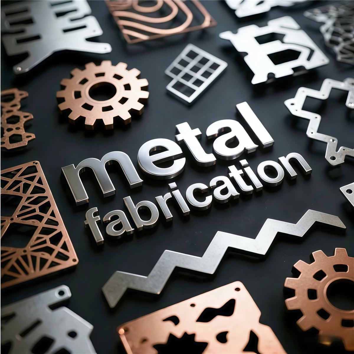
For laser cutting design guide for accurate sheet metal parts, resolve set feature size and spacing before production data is released. Tiny holes, narrow slots, and thin webs concentrate heat and may lose definition. A useful starting point is to keep ordinary holes near or above material thickness, then validate exceptions by grade and quality need. Space features far enough apart to prevent thermal interaction and fragile bridges. If a hole will later locate hardware precisely, consider undersizing it for reaming rather than forcing the laser to perform a machining task. When documenting set feature size and spacing, separate mandatory functional requirements from preferences, then identify the datums, interfaces, cosmetic zones, load paths, and acceptance evidence relevant to this decision. The drawing, CAD model, material callout, finish note, and revision should give one consistent definition of the set feature size and spacing requirement. Apply tight limits only where set feature size and spacing affects fit, motion, safety, sealing, or interchangeability; a blanket tolerance can add setup and inspection cost without improving performance. If uncertainty remains around set feature size and spacing, approve a representative first article before committing production material or tooling.
Control Corners, Kerf, and Pierce Marks
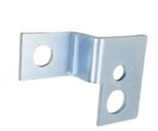
In laser cutting design guide for accurate sheet metal parts, a review of control corners, kerf, and pierce marks must connect geometry, material behavior, tooling access, and inspection. Internal sharp corners are limited by beam and kerf behavior; add radii where a mating part permits them. CAM compensates kerf, but the drawing must describe the required final boundary rather than embed an assumed offset in the model. Locate lead-ins and pierces away from sealing edges and cosmetic faces. Thick plate may show taper, dross, or a heat-affected edge that needs secondary work. When documenting control corners, kerf, and pierce marks, separate mandatory functional requirements from preferences, then identify the datums, interfaces, cosmetic zones, load paths, and acceptance evidence relevant to this decision. The drawing, CAD model, material callout, finish note, and revision should give one consistent definition of the control corners, kerf, and pierce marks requirement. Apply tight limits only where control corners, kerf, and pierce marks affects fit, motion, safety, sealing, or interchangeability; a blanket tolerance can add setup and inspection cost without improving performance. If uncertainty remains around control corners, kerf, and pierce marks, approve a representative first article before committing production material or tooling.

Prepare a Clean Flat Pattern
Within laser cutting design guide for accurate sheet metal parts, treat prepare a clean flat pattern as a controlled engineering choice rather than a drawing afterthought. Supply a closed, coplanar profile at true scale with duplicate lines, open contours, and construction geometry removed. Separate cut, etch, bend, and reference information into clearly named layers when using 2D data. For parts that will be bent, include a formed model and drawing as well as the flat reference, because the fabricator should calculate bend allowances from the actual process. When documenting prepare a clean flat pattern, separate mandatory functional requirements from preferences, then identify the datums, interfaces, cosmetic zones, load paths, and acceptance evidence relevant to this decision. The drawing, CAD model, material callout, finish note, and revision should give one consistent definition of the prepare a clean flat pattern requirement. Apply tight limits only where prepare a clean flat pattern affects fit, motion, safety, sealing, or interchangeability; a blanket tolerance can add setup and inspection cost without improving performance. If uncertainty remains around prepare a clean flat pattern, approve a representative first article before committing production material or tooling.

Design for Nesting and Part Identification
For laser cutting design guide for accurate sheet metal parts, resolve design for nesting and part identification before production data is released. Common material and thickness allow several part numbers to share a sheet, but grain direction, brushed finish, protective film, and cosmetic orientation may restrict rotation. Small parts need micro-joints or controlled sequencing to avoid tipping into slats. Etched identification can aid traceability, yet its location must remain legible after forming and finishing without appearing on a designated cosmetic surface. When documenting design for nesting and part identification, separate mandatory functional requirements from preferences, then identify the datums, interfaces, cosmetic zones, load paths, and acceptance evidence relevant to this decision. The drawing, CAD model, material callout, finish note, and revision should give one consistent definition of the design for nesting and part identification requirement. Apply tight limits only where design for nesting and part identification affects fit, motion, safety, sealing, or interchangeability; a blanket tolerance can add setup and inspection cost without improving performance. If uncertainty remains around design for nesting and part identification, approve a representative first article before committing production material or tooling.
Specify Edge and Inspection Requirements
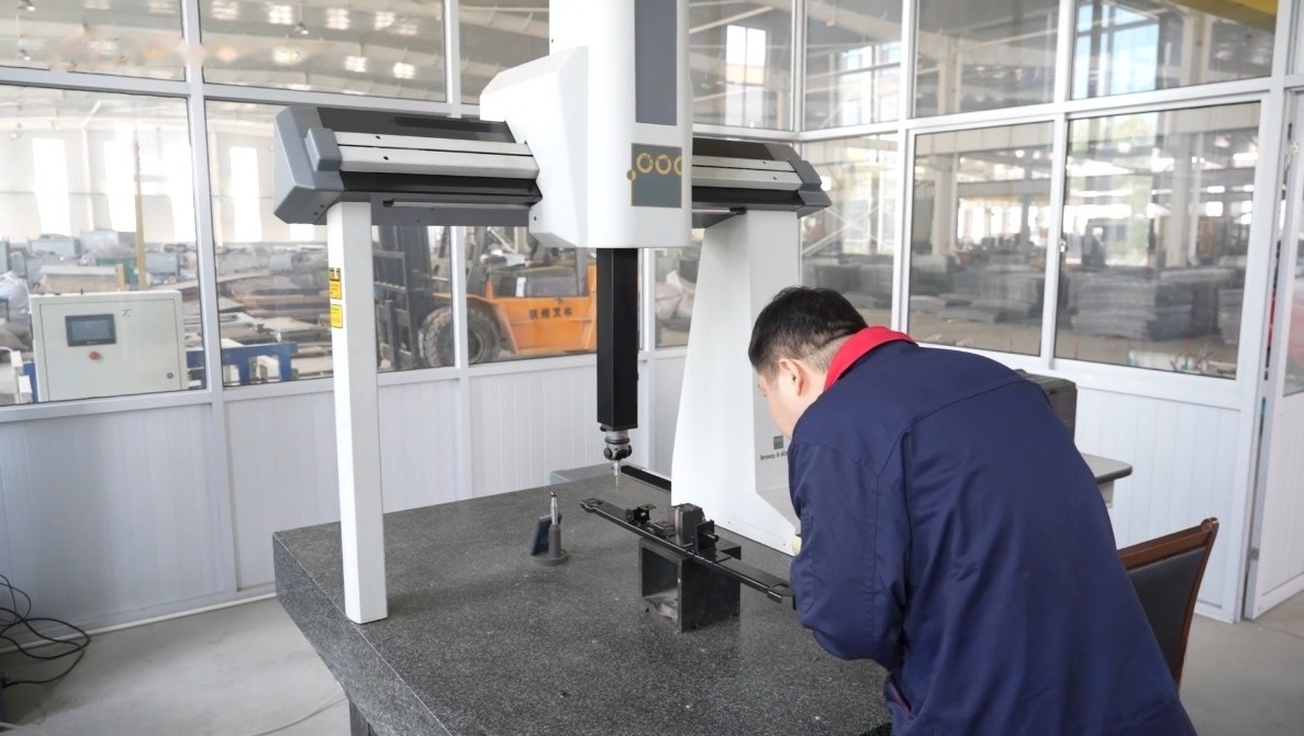
In laser cutting design guide for accurate sheet metal parts, a review of specify edge and inspection requirements must connect geometry, material behavior, tooling access, and inspection. State whether edges may retain light oxide, whether dross must be removed, and what edge break is acceptable. Call out critical cut dimensions and a realistic profile tolerance rather than applying precision to the whole outline. Use calibrated tools, optical measurement, templates, or CMM methods according to feature type. Inspection should occur before bending when later access could hide the cut feature. When documenting specify edge and inspection requirements, separate mandatory functional requirements from preferences, then identify the datums, interfaces, cosmetic zones, load paths, and acceptance evidence relevant to this decision. The drawing, CAD model, material callout, finish note, and revision should give one consistent definition of the specify edge and inspection requirements requirement. Apply tight limits only where specify edge and inspection requirements affects fit, motion, safety, sealing, or interchangeability; a blanket tolerance can add setup and inspection cost without improving performance. If uncertainty remains around specify edge and inspection requirements, approve a representative first article before committing production material or tooling.
Engineering Decision Table
| Condition | Recommendation | Why |
|---|---|---|
| Unproven geometry—laser cutting design guide | Run a representative prototype | Evidence reveals springback, distortion, access, and inspection risks in laser cutting design guide. |
| Functional characteristic—laser cutting design guide | Define datum-based measurement | Critical laser cutting design guide controls need unambiguous acceptance evidence. |
| Cosmetic-only feature—laser cutting design guide | Set an appearance-zone limit | A bounded laser cutting design guide standard avoids unnecessary precision cost. |
| Low volume or changing design—laser cutting design guide | Defer dedicated tooling | A flexible laser cutting design guide route preserves revision freedom. |
| Stable repeat demand—laser cutting design guide | Evaluate dedicated tooling or gauges | Upfront laser cutting design guide engineering can reduce cycle time and variation. |
| Approved input changes—laser cutting design guide | Perform a documented delta review | Substitution can change laser cutting design guide dimensions, corrosion, or appearance. |
| Sector certification required—laser cutting design guide | Confirm compliance before sourcing | XCWY does not claim ISO 13485, IATF 16949, AS9100, or UL. |
RFQ and Drawing Checklist
- Define the functional objective and failure modes—laser cutting design guide.
- Attach matching 3D and revision-controlled 2D files—laser cutting design guide.
- State material grade, temper, thickness, and substitution rules—laser cutting design guide.
- Identify datums and critical-to-function dimensions—laser cutting design guide.
- Separate cosmetic surfaces from nonappearance zones—laser cutting design guide.
- Specify edge break, burr direction, and sharp-edge restrictions—laser cutting design guide.
- Call out finish standard, color, gloss, masking, and test method—laser cutting design guide.
- Provide prototype, launch, and expected annual quantities—laser cutting design guide.
- Agree measurement equipment, sampling, and report format—laser cutting design guide.
- Confirm joining hardware, weld symbols, and assembly sequence—laser cutting design guide.
- Review packaging protection for surfaces and formed features—laser cutting design guide.
- Resolve open DFM questions before approving material or tooling—laser cutting design guide.
Manufacturing Evidence — Laser Cutting Design
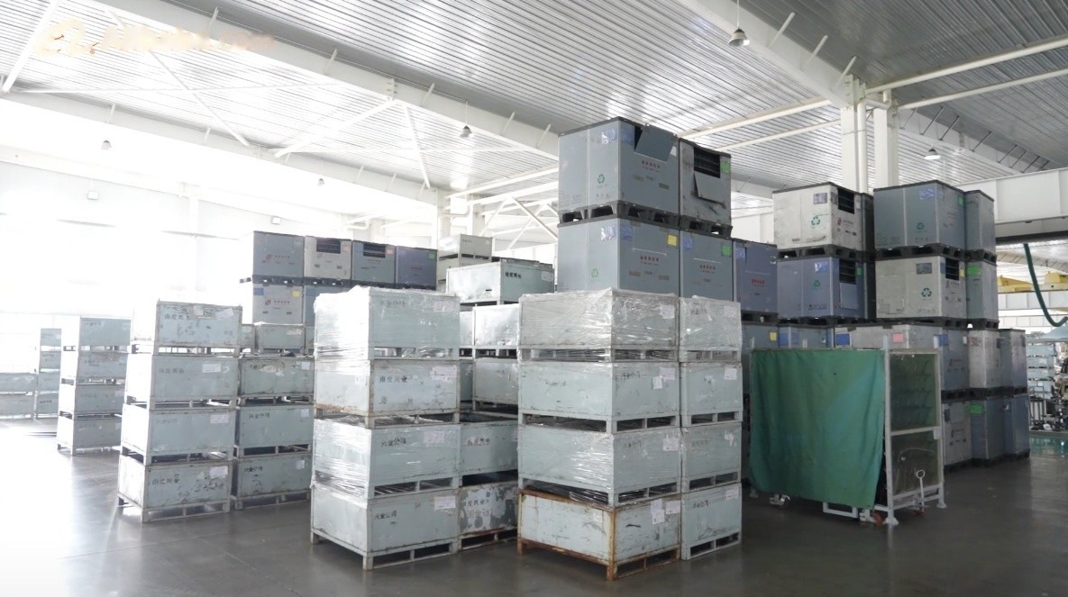
The images below come from the XCWY site asset library and show the plant, equipment, inspection areas and representative parts already published for Laser Cutting Design.
Frequently Asked Questions
When should an engineer request DFM feedback for laser cutting design guide?
Request laser cutting design guide feedback before freezing the drawing and after any material, tolerance, finish, or volume change. An early laser cutting design guide review leaves room to alter geometry before tooling or purchase orders are released.
What files make a laser cutting design guide RFQ technically complete?
For laser cutting design guide, provide matching 3D and controlled 2D data, material grade and temper, quantities, finish, critical dimensions, inspection expectations, and assembly context.
Can XCWY support one laser cutting design guide prototype?
XCWY offers MOQ 1 when the selected laser cutting design guide route is practical. A flexible prototype route may be proposed before production tooling is justified for laser cutting design guide.
How quickly can XCWY quote a laser cutting design guide project?
XCWY targets a laser cutting design guide quotation within three business hours after receiving a complete package. Unclear laser cutting design guide specifications, missing models, or complex tooling require clarification first.
Which quality certification applies to laser cutting design guide?
Work involving laser cutting design guide operates under XCWY’s ISO 9001:2015 system, certificate 34025Q30296R0S. For laser cutting design guide, XCWY does not claim ISO 13485, IATF 16949, AS9100, or UL certification.
What is the most important project-specific check for laser cutting design guide?
Confirm edge quality and minimum-feature expectations on the exact alloy and thickness, especially near the machine’s stated capacity or when reflective copper and aluminum are involved.
Related XCWY Capabilities
Get a Manufacturing Review and Quote
Attach the drawing, revision, material, quantity, critical tolerances, finish and target date. The inquiry is saved in the site database and emailed to the XCWY team.