Metal Surface Finish Guide for Fabricated Parts
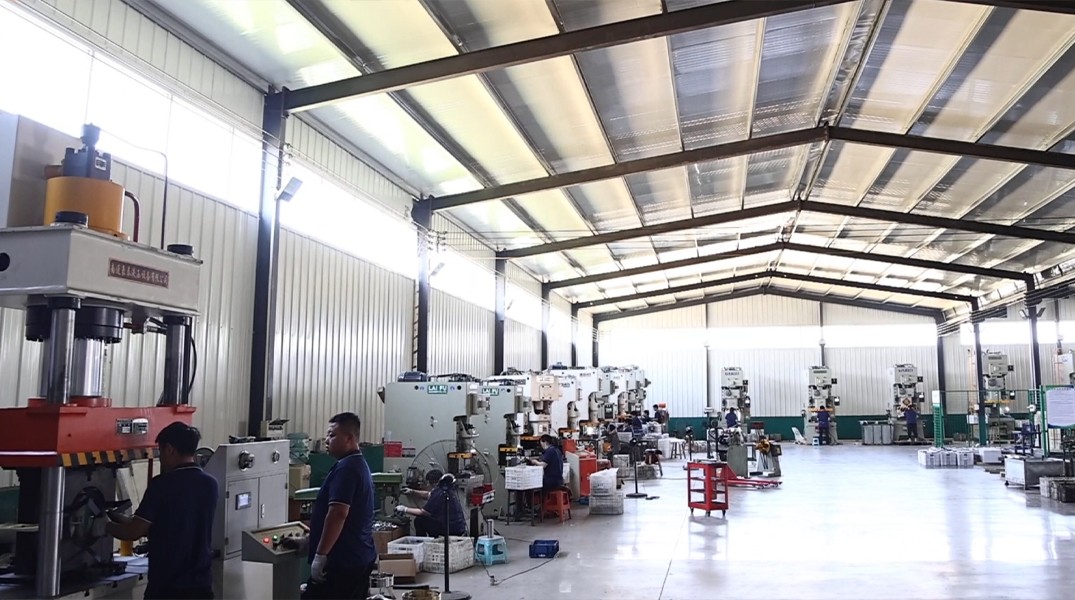
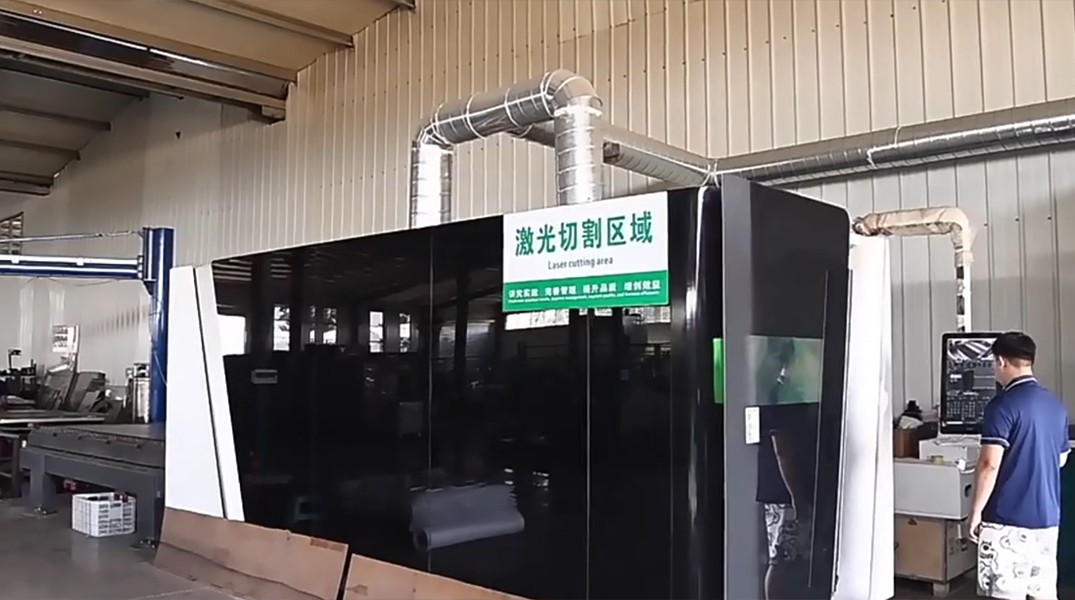
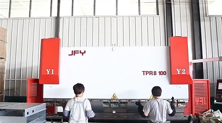
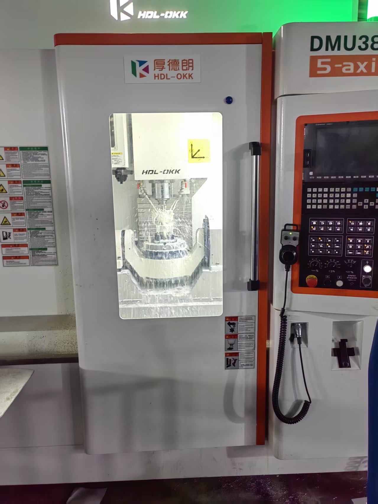
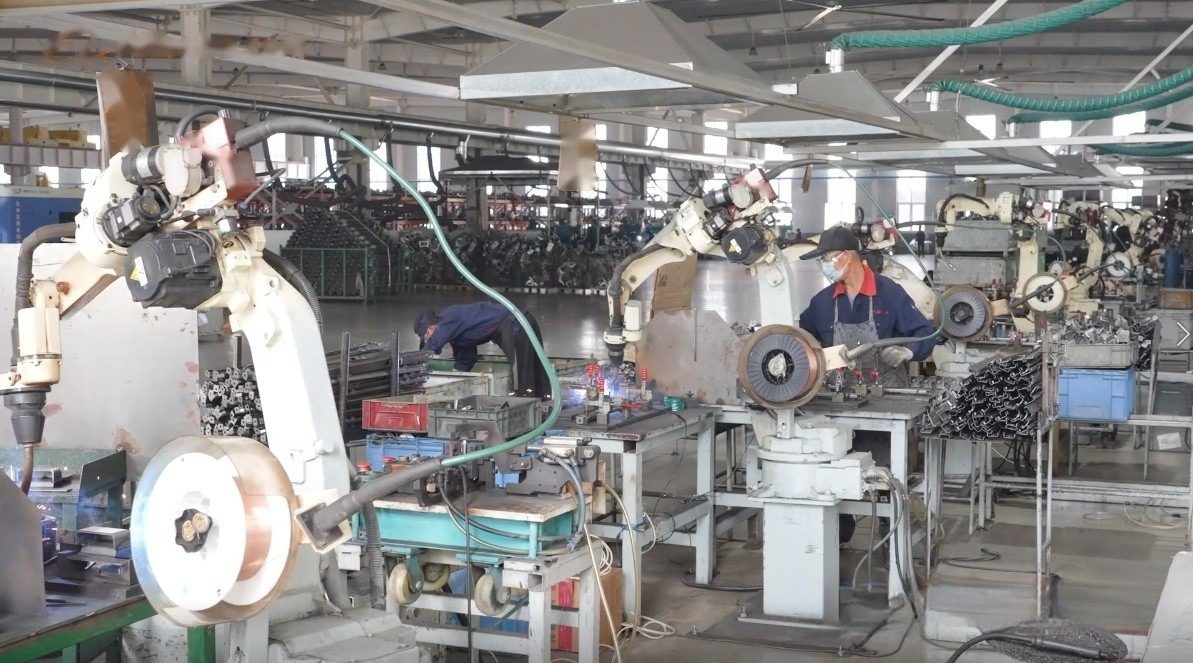
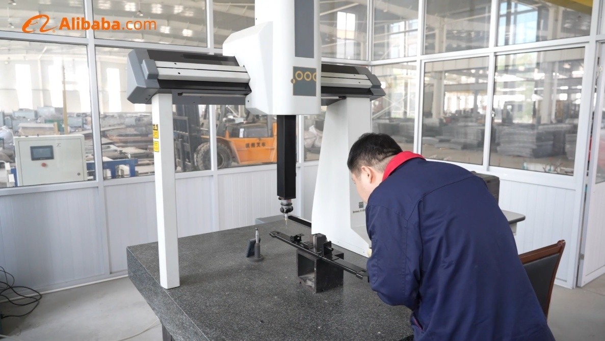
XCWY supports buyers developing custom parts with drawing-based metal manufacturing and practical engineering review. Founded in 1998, the factory operates in a 15,000 m² facility with six production lines and 78 staff. Available processes include 25–400T pressing, 12kW laser cutting, precision press-brake forming, five-axis machining, laser/TIG/MIG/spot welding, and PEM insertion. The 12kW laser cuts carbon steel to 25 mm, stainless steel to 20 mm, aluminum to 12 mm, and copper to 6 mm. A 3,200 mm press brake works to ±0.5° angle capability, while five-axis machining reaches ±0.005 mm under suitable conditions. CMM inspection supports dimensional verification. ISO 9001:2015 registration 34025Q30296R0S covers the quality system. MOQ starts at one piece, NDA handling is available, and complete RFQs are targeted for quotation within three business hours. Chart and guide values are design references; the released drawing controls production and acceptance. This page explains scope, choices, risks, and the information needed for a defensible manufacturing route.
Request a Drawing Review
Attach the drawing, revision, material, quantity, critical tolerances, finish and target date. The inquiry is saved in the site database and emailed to the XCWY team.
Design Scope
A useful engineering program begins by defining the real component family rather than requesting a generic metal part. Typical scope includes finish selection criteria, substrate preparation, color and gloss controls, thickness implications, masking notes, corrosion expectations, and cosmetic acceptance zones. Each item carries different load paths, access needs, appearance zones, and production volumes, so XCWY reviews the assembly context before proposing a process. Important interfaces commonly include threads, PEM hardware, grounding points, seal lands, sliding fits, welds, edges, drainage paths, and customer-visible faces. These features should be dimensioned from stable datums instead of accumulated edge chains. A 3D model helps visualize the assembly, but a revision-controlled 2D drawing remains essential for tolerances, material, finish, burr direction, and inspection notes. Early DFM examines bend relief, inside radii, hole-to-edge distance, tool approach, weld access, hardware installation, and realistic measurement points. Prototype quantities may favor laser cutting and brake forming, while repeat demand can justify hard tooling or progressive operations. Machining is reserved for features that truly need it. XCWY does not assume service loads, environmental class, or legal compliance on the buyer’s behalf. Buyers should provide mating-part data, critical load cases, restricted substances, and any governing standards. That shared definition keeps design responsibility visible, reduces quotation ambiguity, and prevents a low-cost process choice from creating expensive assembly problems later.
Materials and Surface Decisions
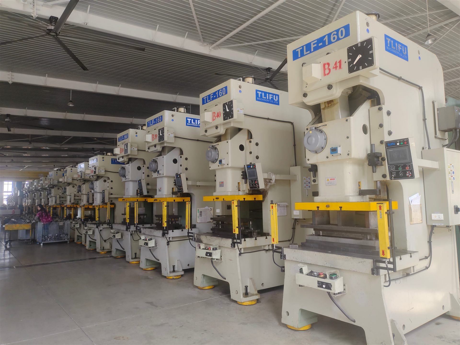
Material selection should connect mechanical function, fabrication behavior, corrosion exposure, appearance, and supply condition. XCWY can process CRS/Q235 and galvanized steel, SS304/316/316L, AL5052/6061, C110/C260, and 65Mn matched to finishes that are chemically and functionally compatible. A grade name alone is not enough: thickness, temper or hardness, applicable standard, grain limits, and certificate expectations should appear in the RFQ. Substitution is not made silently because strength, elongation, conductivity, bend response, weldability, and coating adhesion can change. Surface choices include powder coating, zinc plating, anodizing, brushing, polishing, and passivation, with process-specific callouts rather than vague terms such as standard finish. The drawing should state the process, color or appearance, thickness or class where relevant, masking locations, and cosmetic acceptance zones. Threads, PEM interfaces, grounding points, gasket lands, press fits, and weld areas may require protection from finish buildup. Mixed metals also need review for galvanic risk, especially where moisture can remain. Forming direction and visible grain matter for brushed or polished surfaces, while rack marks and contact points must be assigned to noncritical areas when possible. Finish approval can use a customer standard, measurable specification, or signed sample rather than subjective words such as “good” or “smooth.” Material certificates and finish certificates can be included when requested and defined. These decisions allow sourcing, tooling, forming, welding, and inspection teams to work from the same technical baseline.
Manufacturing Route and Capacity
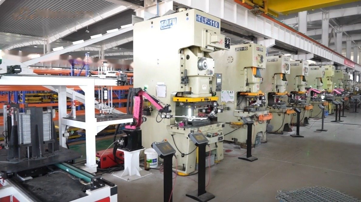
XCWY selects the manufacturing route from geometry, volume, tolerance, material, and finish rather than forcing every design through one machine. Six production lines combine presses from 25 to 400T with a 12kW laser, a 3,200 mm press brake, five-axis machining, welding, hardware insertion, and inspection. The laser has stated cutting limits of 25 mm carbon steel, 20 mm stainless steel, 12 mm aluminum, and 6 mm copper; actual edge quality and speed still depend on grade, thickness, geometry, gas, and acceptance criteria. The brake provides ±0.5° angle capability under appropriate setup, while five-axis machining can reach ±0.005 mm where part shape, fixturing, material stability, and measurement method support it. Prototype blanks can validate fit before tooling investment. Higher volumes may move to compound, transfer, or progressive stamping after demand and tool economics are confirmed. Laser, TIG, MIG, and spot welding are available, with sequence and fixturing planned to limit distortion. PEM insertion can consolidate assembly, but hole preparation, sheet hardness, edge distance, and push-out needs must be specified. Process transitions are documented so that cut parts, formed parts, weldments, inserted hardware, and finished goods remain linked to the correct revision. The resulting route aims for repeatability without claiming that every advertised machine capability applies to every feature.
Quality Planning and Failure Control
Quality planning starts with likely failures, not with a final inspection checklist. Relevant concerns include peeling from poor pretreatment, white rust, color mismatch, coating in threads, rack marks on visible areas, staining after passivation, and galvanic attack at mixed metals. XCWY reviews which characteristics prevent these outcomes, how those characteristics are produced, and which method can verify them. CMM inspection is available for suitable dimensional features, while dedicated gauges, calibrated hand tools, visual standards, coating tests, fit checks, and functional fixtures may be more appropriate elsewhere. The control plan should identify critical dimensions, sampling level, inspection stage, measurement condition, and reaction path. Welded or formed assemblies need datums that remain stable after processing; flexible edges are poor inspection references. Cosmetic requirements benefit from defined viewing distance, lighting, allowed defect size, and zone classification. Material identity, hardware type, finish batch, and revision status can be captured according to the agreed traceability level. First-article evidence is useful before volume release, and PPAP Level 3 is available when requested, particularly when the customer supplies the required format and submission expectations. XCWY is ISO 9001:2015 registered under 34025Q30296R0S, but it is not IATF, ISO 13485, AS9100, or UL certified. Any sector-specific approval or product certification remains a separately defined customer requirement and must not be inferred from the quality-system certificate.
RFQ, Documentation, and Commercial Handoff
A complete custom parts RFQ shortens review time and produces a more comparable quotation. The preferred package contains released finish specification stating process, standard, color, gloss, thickness or class, pretreatment, masking, cosmetic zones, test method, sampling, and approved reference panel. Include target quantity, prototype and annual demand, delivery location, desired schedule, and whether tooling is customer-owned. Native CAD plus a readable PDF reduces interpretation risk; conflicting dimensions or revisions should be resolved before release. XCWY targets a quotation within three business hours after receiving complete information, although complex tooling, unusual testing, or incomplete specifications may require clarification before a firm offer. MOQ begins at one piece, enabling fit checks or engineering samples, but one-piece economics should not be projected onto production demand. NDA support is available for confidential custom parts files. Change control matters after award: material, tolerance, finish, hardware, packaging, or source changes should follow an agreed approval path. PPAP Level 3 can be prepared when requested, but its contents, sample quantity, timing, and customer templates belong in the order scope. Packaging should address part nesting, moisture, edge protection, cosmetic separation, and label traceability rather than being treated as an afterthought. XCWY will not invent customer names, approvals, test reports, or end-product certifications. A disciplined handoff aligns the released design, commercial assumptions, inspection evidence, and shipment method before production begins. All values on this page are design references; the released drawing controls production and acceptance.
Specifications and Scope
| Quality system | ISO 9001:2015 registration 34025Q30296R0S |
|---|---|
| Operating history | manufacturing support since 1998 |
| Factory scale | capacity within a 15,000 m² facility, six lines, and 78 staff |
| Pressing | press range from 25T through 400T |
| Laser cutting | 12kW limits: carbon steel 25 mm, stainless 20 mm, aluminum 12 mm, copper 6 mm |
| Press brake | forming on a 3,200 mm brake with ±0.5° angle capability under suitable conditions |
| Five-axis machining | precision capability to ±0.005 mm when geometry, setup, and inspection support it |
| Joining | laser, TIG, MIG, and spot welding, plus PEM insertion |
| Inspection | dimensional verification supported by CMM inspection |
Typical Applications
Finish Selection Workshops
XCWY reviews this application against the released drawing, material, quantity, interfaces, finish and inspection requirements before proposing a manufacturing route.
Drawing Callout Preparation
XCWY reviews this application against the released drawing, material, quantity, interfaces, finish and inspection requirements before proposing a manufacturing route.
Corrosion-Risk Review
XCWY reviews this application against the released drawing, material, quantity, interfaces, finish and inspection requirements before proposing a manufacturing route.
Cosmetic Zone Definition
XCWY reviews this application against the released drawing, material, quantity, interfaces, finish and inspection requirements before proposing a manufacturing route.
Masking Plan Development
XCWY reviews this application against the released drawing, material, quantity, interfaces, finish and inspection requirements before proposing a manufacturing route.
Mixed-Metal Assessment
XCWY reviews this application against the released drawing, material, quantity, interfaces, finish and inspection requirements before proposing a manufacturing route.
Supplier Quote Comparison
XCWY reviews this application against the released drawing, material, quantity, interfaces, finish and inspection requirements before proposing a manufacturing route.
Incoming Inspection Planning
XCWY reviews this application against the released drawing, material, quantity, interfaces, finish and inspection requirements before proposing a manufacturing route.
Choosing a Finish Against a Corrosion Environment
Finish selection should start from the environment the part lives in, not from a preferred finish. Two questions decide most of it: which corrosivity category the part sits in, and what the coating has to survive. Answer those first and the finish choice usually narrows itself.
Start from the corrosivity category, not the finish name
The ISO 12944 series handles this in two steps. One part of the series sorts an environment into a corrosivity category; ISO 12944-5 then matches a protective paint system to that category. A part inside a heated cabinet and a part on a marine deck can use the same steel grade and still need completely different coating systems.
| Service environment | What actually drives the choice |
|---|---|
| Interior, heated, low humidity | Appearance and handling protection — corrosion is not the binding constraint |
| Rural or light urban | Atmospheric moisture and mild pollution |
| Urban or industrial | Sulphur and particulate pollution, plus condensation cycling |
| Coastal, low salinity | Chloride deposition — driven by distance from the water and prevailing wind |
| Marine or aggressive industrial | Continuous chloride or chemical exposure; pretreatment quality usually decides the outcome |
The rows above are the environment classes the ISO 12944 series is built around. Which category your site falls into is a design decision that belongs on the drawing — not a default a finishing shop should be left to choose.
What 500–1,000 hours of salt spray does and does not tell you
XCWY’s published figure for powder coating over galvanized steel is 500 to 1,000+ hours of neutral salt spray. That result is produced under ASTM B117, which runs a continuous neutral salt fog — the standard specifies a 5% sodium chloride solution at controlled temperature and pH, with the sample held at a fixed angle.
Two honest caveats come with any salt-spray number. First, it is an accelerated test rather than a service-life predictor: the chamber cycles continuously between wet and dry, while a real part spends most of its life dry, and the correlation between hours in fog and years in service is weak. Second, the result belongs to a coating system — steel grade, pretreatment, primer and topcoat together — not to a finish name. Writing “powder coated” on a drawing specifies a process; it does not specify a corrosion performance.
Edge coverage is where thin-film finishes fail first
Sprayed and dipped coatings thin out at sharp edges and corners, because surface tension pulls material away from a tight radius. That makes edge preparation a finishing decision rather than a deburring detail: a small radius holds film, a knife edge does not. Where a part will be handled, sealed, or exposed, specify both a radius and a deburring requirement instead of leaving either to assumption.
Specify the system, not the finish name
- State the environment — interior, coastal or marine — rather than naming a colour.
- State the pretreatment. On steel this is usually the difference between passing and failing.
- State film build and its tolerance, not only the coating type.
- State where the coating must not go — masked threads, mating faces, weld areas and grounding points.
- State the acceptance test and who runs it, so pass or fail is agreed before production starts.
- Say whether the part is re-formed after coating. Coating then bending cracks the film; bending then coating does not.
Where finishing cost actually lands
Finishing is normally a per-piece adder rather than a share of the piece price. Published worked examples put the individual steps in a narrow band: zinc plating at roughly $0.12 per piece on a $2.00 stamped part, export-grade packaging at about $0.08, and freight forwarding at roughly $0.65. Individually small — together they lift the landed cost to about $2.85, roughly 42% above the bare piece price. Ask for finishing as separate line items so you can see which step is doing the work before you decide to remove it.
About these figures. The salt-spray hours quoted here are XCWY’s own published capability. The cost figures are third-party published industry benchmarks and are not XCWY prices. Coating performance depends on the whole system and on the service environment; confirm the specification against your drawing before release.
Risks Buyers Should Resolve Before Release
| Risk | Effect | Control |
|---|---|---|
| peeling from poor pretreatment | Define a functional datum and verify the feature at the controlling process stage. | Define a functional datum and verify the feature at the controlling process stage. |
| white rust | Specify material condition and validate forming with samples before volume release. | Specify material condition and validate forming with samples before volume release. |
| color mismatch | Control weld or forming sequence with appropriate fixtures and an agreed inspection condition. | Control weld or forming sequence with appropriate fixtures and an agreed inspection condition. |
| coating in threads | State finish preparation, masking, thickness, and acceptance evidence on the drawing. | State finish preparation, masking, thickness, and acceptance evidence on the drawing. |
| rack marks on visible areas | Use revision-linked hardware identification plus incoming and in-process checks. | Use revision-linked hardware identification plus incoming and in-process checks. |
| staining after passivation | Remove or control burrs with direction, edge, and handling requirements. | Remove or control burrs with direction, edge, and handling requirements. |
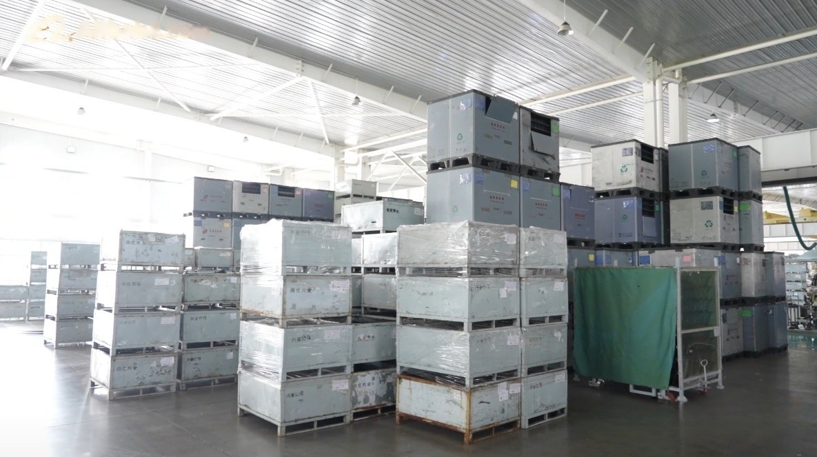
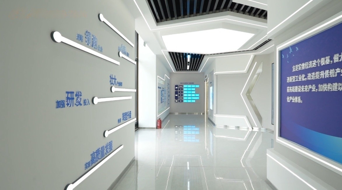
Manufacturing Evidence — Surface Finishing
The images below come from the XCWY site asset library and show the plant, equipment, inspection areas and representative parts already published for Surface Finishing.
Frequently Asked Questions
What files are needed to quote custom parts?
Send the 2D drawing, 3D model when available, quantities, material, finish, tolerance notes, inspection expectations, packaging, and destination. Conflicting revisions should be resolved before a firm quotation.
Can XCWY make a single prototype part?
Yes. The MOQ starts at one piece. Prototype routing may use laser cutting, brake forming, machining, welding, or PEM insertion before dedicated tooling becomes economical.
How quickly can XCWY quote custom parts?
For a complete custom parts RFQ, XCWY targets a quotation within three business hours. Tooling studies, missing standards, unusual tests, or unclear acceptance criteria can extend review.
Which metals are available?
The material range includes CRS, Q235, galvanized steel, SS304, SS316, SS316L, AL5052, AL6061, C110, C260, and 65Mn. Final choice depends on function and released specifications.
Which finishes can be specified?
Available options include powder coating, zinc plating, anodizing, brushing, polishing, and passivation. Compatibility, masking, thickness, appearance, and test requirements should be defined.
Is PPAP available?
PPAP Level 3 is available when requested. Buyers should state templates, submission level, sample quantity, timing, control-plan expectations, and approval workflow in the RFQ.
Which certifications do not apply to custom parts?
XCWY holds ISO 9001:2015 registration 34025Q30296R0S for its quality system. The offer does not claim IATF, ISO 13485, AS9100, or UL certification.
Does this page override a drawing?
No. Content about custom parts is design-reference information only. The released drawing controls production and acceptance, including material, dimensions, tolerances, finish, inspection, and revision.
Continue the Engineering Review
Get a Manufacturing Review and Quote
Attach the drawing, revision, material, quantity, critical tolerances, finish and target date. The inquiry is saved in the site database and emailed to the XCWY team.